Foundation Drawings: Footings, Rafts and Layouts
Lesson 12 of 32 · 6 min read
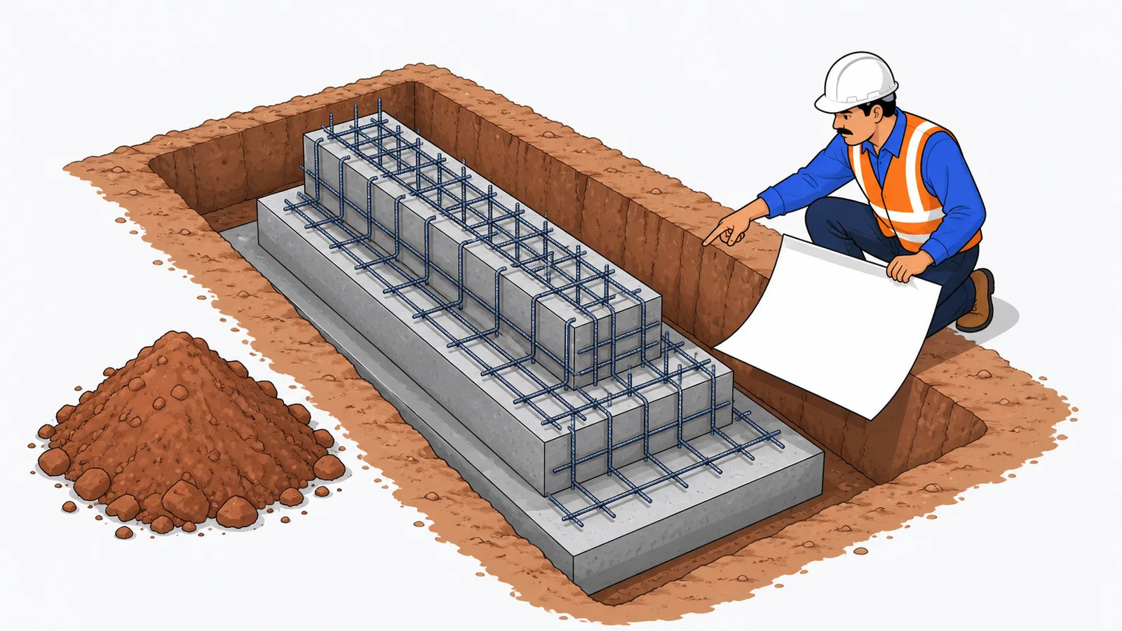
Everything in this module sits on work that disappears. A week after casting, every footing on your project is under backfill, and the only proof of what you built is the drawing plus your pour records. That is why foundation drawings are read with a different level of paranoia than any other sheet — and why, in an era where RERA-registered projects must defend structural quality for five years after handover, your documented compliance with these sheets is a genuine financial shield.
The two documents you will always have
A foundation package in an Indian structural set has two core parts:
- The foundation layout plan — a plan of the whole footprint showing every footing, raft and pile cap in position, tied to the same grid the columns use. It locates; it rarely sizes.
- Footing sections and schedules — the details that give depth, reinforcement, PCC and levels for each footing type.
You need both. A layout without its sections cannot be excavated to the right depth; a section without the layout cannot be placed in the right spot.
The foundation family
- Isolated (pad) footings — one column, one pad. The default for modest loads and decent soil.
- Combined footings — two or more columns sharing a pad because their individual pads would overlap or a boundary cuts one short.
- Strip footings — a continuous ribbon under a wall: boundary walls, load-bearing masonry, retaining walls.
- Rafts — one slab under everything, used when loads are heavy or soil is weak; universal under high-rise cores.
- Piles and pile caps — when the safe soil is too deep to reach by open excavation.
Which one you get is the structural consultant's decision from the soil report — but which one you are looking at should be readable in seconds from the layout plan.
Reading a layout: the dashed-line rule
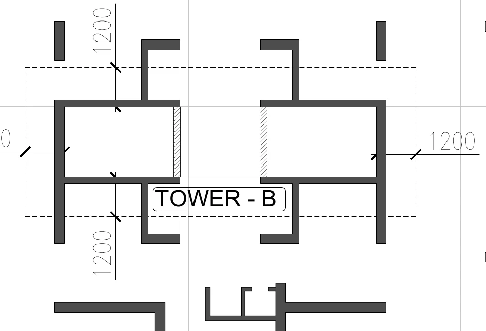
How to read this
- The solid dark shapes are the core/shear walls of Tower B in plan — the boxed label TOWER - B sits directly on the cluster.
- The dashed rectangle enclosing them is the footing edge below ground. Dashed linework on a plan means hidden — below (or above) the level being drawn.
- Read the 1200 dimensions with tick marks: the footing edge projects 1200 mm beyond the wall faces. Excavation, footing shuttering and later the wall shutter are all set out from this offset.
- Note what is missing: no depth, no reinforcement, no levels. A layout plan locates; the sections and schedules elsewhere in the set size and reinforce.
This crop is from the foundation layout of Project B, a multi-tower residential project. The solid dark shapes are the core walls of Tower B rising through the foundation. The dashed rectangle enclosing the whole cluster is the footing edge below — dashed because once cast and buried you will never see it; on plans, dashed linework means hidden below or above the cut. The 1200 dimensions with tick marks record that the footing edge projects 1200 mm beyond the wall faces on each side.
That offset is the working number for three different teams: excavation must go at least 1200 mm plus working space beyond the wall line, the shuttering edge is set at the dashed line, and the wall shutter is later set back 1200 from it. Confuse the wall line with the footing line — the single most common foundation setting-out error — and the whole core shifts.
Notice also what the layout does not say: no depth, no bars, no levels. For that, you go to a section.
Reading a footing section
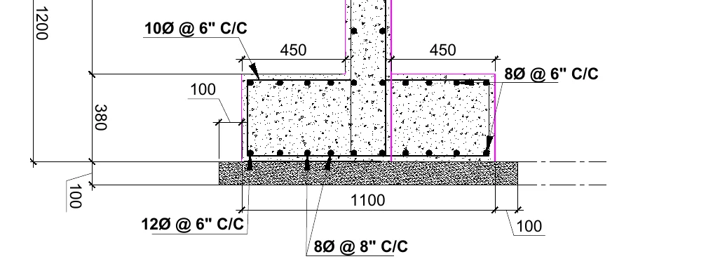
How to read this
- Find the stem coming down into the footing. It projects 450 to each side, and the base reads 1100 overall — so the stem is 1100 - 450 - 450 = 200 mm thick.
- The footing is 380 deep on a 100 thick PCC layer projecting a further 100 each side. The PCC is the clean working surface that lets the design use 50 mm cover instead of 75.
- Bottom callouts: 12Ø @ 6 in C/C are the main bars across the width (12 mm at 150 mm), and 8Ø @ 8 in C/C the longitudinal distribution bars seen end-on as dots (8 mm at 200 mm). Metric diameters, imperial spacings — convert before you cut.
- The top face carries 10Ø @ 6 in C/C, with 8Ø @ 6 in C/C on the far face: this footing is meshed top and bottom, not bottom only.
- The 1200 dimension running up the stem is the wall continuing above the crop — the footing story ends at the 380.
This is an RCC strip footing under a boundary wall on Project A, the nine-storey commercial tower. Walk it:
- The stem comes down into a footing that projects 450 mm to each side (the toe and the heel). The overall base reads 1100, so the stem is 1100 − 450 − 450 = 200 mm thick — the section lets you derive what it does not label.
- The footing is 380 mm deep and sits on a 100 mm PCC (plain concrete) levelling course that projects a further 100 mm each side. PCC is not structural — it is a clean, level casting surface. It also has a code consequence: IS 456 requires a minimum nominal cover of 50 mm in footings, and commonly applied practice increases this to 75 mm where concrete is cast directly against earth with no PCC. The Rs. 4,000-odd of lean concrete under a footing run protects far more than it costs.
- Now the reinforcement callouts, and the trap: 12Ø @ 6" C/C for the main bottom bars across the width, 8Ø @ 8" C/C for the longitudinal distribution bars (the dots you see end-on), 10Ø @ 6" C/C in the top face and 8Ø @ 6" C/C on the other face. Diameters are metric millimetres; spacings are imperial inches. This mixed convention is still common on Indian sheets, especially boundary-wall and compound-wall details. 6 in is taken as 150 mm and 8 in as 200 mm on site. A fitter who reads 6 as 60 mm, or lays 8 mm bars where 12 mm main bars belong, changes the steel quantity by half — in either direction.
- The 1200 running up the stem is simply the wall continuing above the crop; this lesson stops at the footing.
Footings like this one are meshed top and bottom — do not assume bottom-only steel just because textbook pad footings show one mesh.
The worked number: 10 metres of this footing
Take a 10 m run of the excerpt's footing and build its quantities the way the QS course's PCC and footings lesson does:
| Item | Calculation | Result |
|---|---|---|
| Footing concrete | 1.10 x 0.38 x 10.0 | 4.18 m³ |
| PCC below (1100 + 100 + 100 wide) | 1.30 x 0.10 x 10.0 | 1.30 m³ |
| Main bars 12Ø @ 150: count | 10.0 / 0.15 + 1 = 67 bars | 67 nos |
| Main bar length (1100 − 2 x 50 cover) | approx. 1.00 m each | 67.0 m |
| Main bar weight (12² / 162 = 0.89 kg/m) | 67.0 x 0.89 | 59.6 kg |
| Distribution 8Ø @ 200: rows across 1.0 m | 1.0 / 0.2 + 1 = 6 rows | 6 x 10 m = 60 m |
| Distribution weight (8² / 162 = 0.395 kg/m) | 60 x 0.395 | 23.7 kg |
| Bottom steel total | 59.6 + 23.7 | 83.3 kg |
At an indicative mid-2026 rebar price of Rs. 52–64 per kg (check current city quotations), the bottom steel alone in this 10 m run is Rs. 4,300–5,300 — and the top mesh is measured the same way. Every number came off one small section; nothing was assumed. That is the standard your own reading should hit, because once buried, this table plus your pour register is the only defence when a structural audit or a final-account dispute asks what went into the ground.
Common mistakes
- Excavating to the wall line, not the dashed footing line. The 1200 offsets exist precisely so you do not have to guess.
- Skipping or thinning the PCC. It is small money and large consequence: cover control, clean steel, honest levels.
- Reading inch spacings as millimetres (or vice versa). If a spacing has a double-quote mark after it, it is inches; confirm the site convention before the first bar is cut.
- Assuming all footings on the layout are the same type. One plan can carry pads, combined footings and a raft; each mark keys to its own section.
- No photographic record before backfill. Photograph each footing with steel fixed, tape in frame, and file it against the footing mark — five minutes that has settled real disputes.
What comes next
The footing exists to receive a column. The next lesson climbs one step up the load path — to the column layout plan and the schedule that tells you, zone by zone, what is inside every column on the job.
Key takeaways
- A foundation package always splits into a layout plan (position, tied to the column grid) and sections/schedules (depth, bars, PCC, levels) — you need both to build one footing.
- Dashed linework on a foundation plan is the buried footing outline; solid shapes are walls and columns rising through it. Set out excavation from the dashed line plus its stated offsets.
- IS 456 requires 50 mm minimum nominal cover in footings, and practice increases it to 75 mm where concrete is cast directly against earth — which is what the PCC layer is protecting you from.
- Older Indian details mix millimetre bar diameters with inch spacings (6 in = 150 mm, 8 in = 200 mm); misreading the units halves or doubles the steel.
- Foundations cannot be inspected after backfill — measured quantities, pour records and pre-backfill photographs against each footing mark are your only durable evidence.
Verify on site
- Verify the footing outline being excavated is the dashed line plus stated offsets, not the wall centreline.
- Check PCC thickness and projection against the section before footing steel is placed.
- Convert every inch spacing to millimetres on a pour card and get the bar bender to repeat it back.
- Measure cover blocks against the 50 mm footing requirement (75 mm if no PCC) before pouring.
- Confirm top mesh is present where the section shows it — top steel in footings is a known omission.
- Photograph fixed steel with a tape in frame, tagged to the footing mark, before any backfill.
Check your understanding
5 questions. Answering them marks this lesson complete — results stay on your device.
Want the free certificate?
The whole course is free and open — no signup needed to learn. Enter your details only if you want us to track your progress on this device and issue a named certificate after the final assessment.