Column Layouts and the Column Schedule
Lesson 13 of 32 · 6 min read
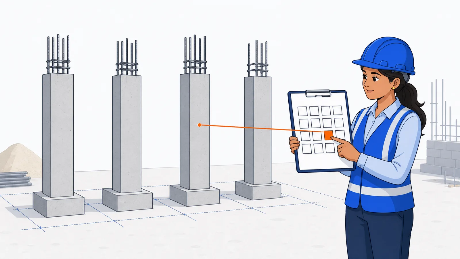
Ask a site engineer "what is inside column C13?" and watch what they reach for. The wrong answer is memory. The right answer is a two-sheet move: the column location plan to find it, then the column schedule to read it — for the correct height zone. Columns are the building's spine and among its most steel-dense members; a misread schedule entry repeats identically on every floor until someone catches it. This lesson makes that two-sheet move automatic, using both of our real projects — because they schedule columns in two completely different formats, and you will meet both in your career.
Step 1 — locate: the column location plan
How to read this
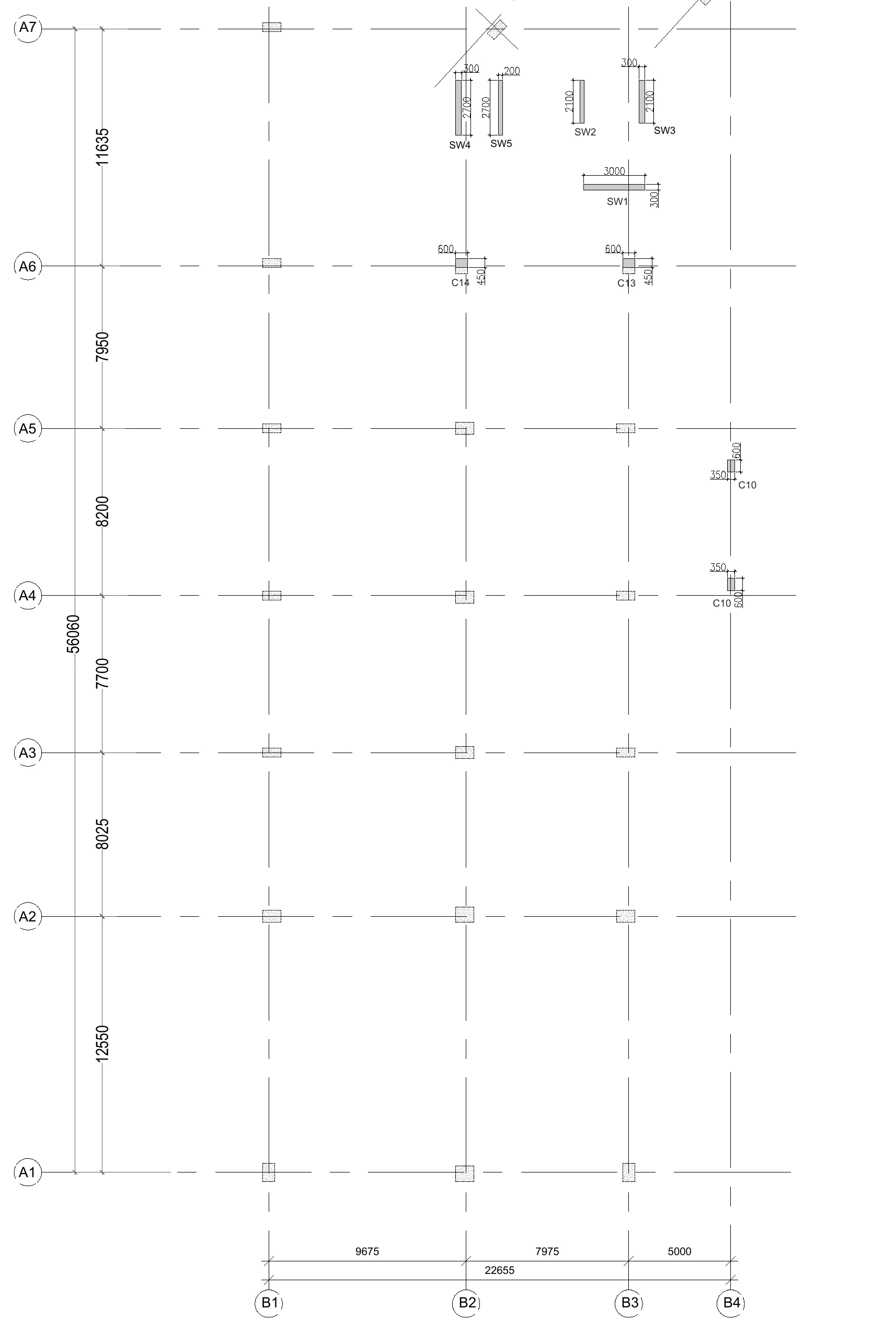
- Orient with the grid bubbles: A1 at the bottom up to A7, B1 to B4 across. The chained distances — 12550, 8025, 7700, 8200, 7950, 11635 — sum to the overall 56060. Check the closure yourself.
- Find C14 and C13 on gridline A6: each drawn 600 long and 450 deep, with offset dimensions tying column faces to the grids.
- C10 appears twice near gridline B4 at 350 x 600 — the same mark repeats wherever that column type occurs.
- The longer grey rectangles labelled SW1 to SW5 are shear walls: SW1 3000 x 300, SW4 300 x 2700, SW5 200 x 2700, SW2 and SW3 at 2100. Read thickness and length off each.
- Note the plan gives position and plan size only — reinforcement lives in the schedule. You need both sheets to build one column.
This is Project A's column location plan (the nine-storey commercial tower). Grid bubbles run A1 at the bottom to A7 at the top and B1 to B4 across, with chained distances 12550, 8025, 7700, 8200, 7950 and 11635 summing to the overall 56060. Columns sit at grid intersections as small hatched rectangles; the marks that fall inside this crop are C14 and C13 on gridline A6 — each 600 long and 450 deep, with offset dimensions tying their faces to the grids — and C10 near gridline B4, 350 x 600, appearing twice. The longer grey rectangles are shear walls: SW1 at 3000 x 300, SW4 at 300 x 2700, SW5 at 200 x 2700, SW2 and SW3 at 2100 long. Every member on the full sheet carries a mark; module 2's setting-out lesson taught you to fix each one by grid plus offset.
One habit to build now: check the chains close. 12550 + 8025 + 7700 + 8200 + 7950 + 11635 = 56060 — it closes. Then put this sheet next to the terrace framing plan from lesson 1 and read its overall figure. On our copies the framing sheet's overall appears to read 56065 against 56060 here — a 5 mm-scale mismatch between two sheets of the same set. Whether that is a drafting slip or a print artefact, the response is the same: you do not choose a number silently. You log it and ask. Tiny, boring, and exactly the discipline that separates engineers whose bills survive scrutiny.
Step 2 — read: the schedule, Project A style
How to read this
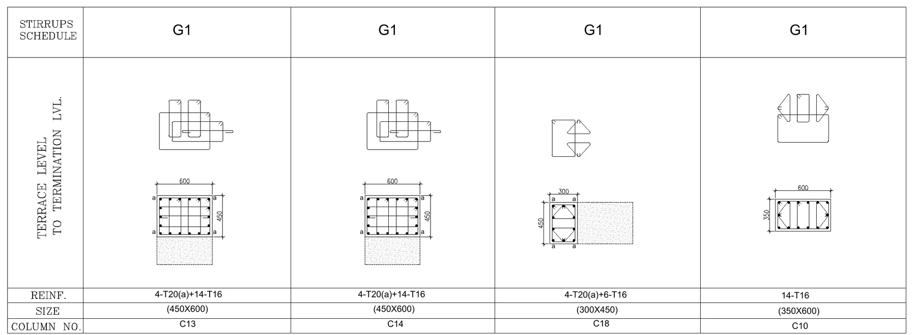
- Read the bottom row first: COLUMN NO. gives C13, C14, C18 and C10. Find your column, then read straight up.
- SIZE row: C13 and C14 are (450X600), C18 is (300X450), C10 is (350X600) — plan dimensions in mm.
- REINF. row: 4-T20(a)+14-T16 means 4 bars of 20 mm plus 14 of 16 mm — 18 verticals. The (a) keys the 20 mm bars to the positions lettered a on the drawn section above.
- In the drawn section, count the bar dots — the count must match the REINF. row — and note how the link shapes drawn above wrap the bars.
- The G1 header keys the stirrup set to a separate stirrups schedule, and the margin note TERRACE LEVEL TO TERMINATION LVL. limits this strip to that height zone — lower zones have their own entries.
Project A schedules columns as a strip of drawn cross-sections above data rows. Read any column bottom-up: find its mark in the COLUMN NO. row, then read straight up.
- C13: SIZE (450X600), REINF. 4-T20(a)+14-T16, stirrup set G1.
- C14: identical — (450X600), 4-T20(a)+14-T16.
- C18: (300X450), 4-T20(a)+6-T16 — 10 bars.
- C10: (350X600), 14-T16 — no 20 mm bars at all.
Decode 4-T20(a)+14-T16: 4 bars of 20 mm diameter plus 14 bars of 16 mm — 18 vertical bars total. T is the high-yield deformed bar prefix (Fe500-class sariya on modern jobs; the general notes confirm the grade). The (a) is the clever part: in the drawn section above the row, the corner positions are lettered a — so the four 20 mm bars go in the marked corner positions, and the drawn dots show exactly where all 18 bars sit and how the links wrap them. Count the dots in the section; they must equal the REINF. row. If they do not, that is an RFI, not a shrug.
Two more reading rules on this strip:
- The left margin reads TERRACE LEVEL TO TERMINATION LVL. — this table column governs only that height zone. The same C13 has other entries for lower zones with heavier steel; columns shed load (and bars) as they rise. Reading the wrong zone's entry is the classic column-schedule error, so always confirm the zone band before lifting numbers.
- The G1 tag keys to a separate stirrups schedule that converts the letter into legs, diameter and spacing (the BBS module decodes those in full).
Step 3 — the same job in a different suit: Project B
How to read this
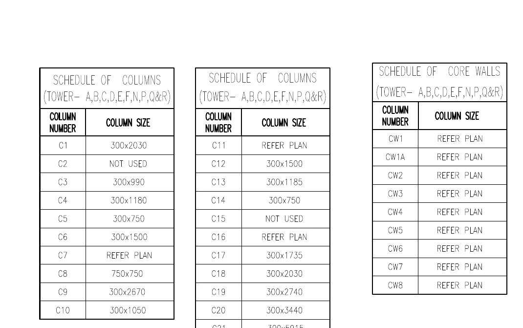
- The heading — SCHEDULE OF COLUMNS (TOWER- A,B,C,D,E,F,N,P,Q&R) — makes one table serve ten towers; a mark means the same member type in each.
- Read the sizes: C1 300x2030, C8 750x750, C20 300x3440. Mostly 300 thick blade columns — a shear-wall residential system, unlike Project A's 450 x 600 commercial columns.
- C2 and C15 read NOT USED: marks retired during design, never renumbered. Never invent a member to fill the gap.
- C7, C11 and C16 read REFER PLAN — irregular members whose geometry is drawn, not tabulated. The whole SCHEDULE OF CORE WALLS (CW1 to CW8) works this way.
- Compare with Project A's drawn-section format: same job — locate, size, reinforce — different packaging. And note both projects have a C13, with completely different sizes: marks are project-local.
Project B — the multi-tower residential project — schedules columns as plain tables: COLUMN NUMBER against COLUMN SIZE, headed SCHEDULE OF COLUMNS (TOWER- A,B,C,D,E,F,N,P,Q&R). One schedule serves ten towers; a mark means the same member type in every listed tower. Read the sizes and you can feel the different structural system: C1 is 300x2030, C9 is 300x2670, C20 is 300x3440 — long, 300 mm thick blade columns, typical of shear-wall residential design, against Project A's chunky 450 x 600 commercial columns.
And the edge cases, which are the real lesson:
- C2 and C15 read NOT USED. Marks retired during design and never renumbered. The gap is deliberate — never "helpfully" assign a size to a missing mark.
- C7, C11 and C16 read REFER PLAN, as do all core walls CW1 to CW8 in the adjacent SCHEDULE OF CORE WALLS. These members are irregular; their geometry is drawn on the plan, not tabulated. The schedule is honestly telling you it is not the whole truth.
Now the trap that pays for this whole lesson: both projects have a column called C13. In Project A, C13 is 450 x 600 with 18 bars. In Project B, C13 is 300 x 1185. Column marks are project-local labels, never industry standards. An engineer who carries "C13 means 450 x 600" from one job to the next is walking around with a loaded error.
The worked number: what one schedule cell costs
Take Project A's C13 in the terrace zone — 4-T20(a)+14-T16 — and price its vertical steel per storey. Bar weight per metre is d²/162 (d in mm):
| Step | Calculation | Result |
|---|---|---|
| 20 mm bar weight | 20 x 20 / 162 | 2.47 kg/m |
| 16 mm bar weight | 16 x 16 / 162 | 1.58 kg/m |
| 4 bars of T20 | 4 x 2.47 | 9.88 kg/m |
| 14 bars of T16 | 14 x 1.58 | 22.12 kg/m |
| Vertical steel, per metre of column | 9.88 + 22.12 | 32.0 kg/m |
| Per 3.0 m storey height | 32.0 x 3.0 | 96 kg |
| Indicative cost at Rs. 52–64/kg (mid-2026; use current quotes) | 96 x 52 to 96 x 64 | Rs. 5,000–6,100 |
That is one column, one storey, verticals only — before links, laps and the heavier lower zones. Multiply across a floor plate of thirty columns and the schedule strip you just learned to read is pricing several lakhs of steel per floor. It is also your billing defence: when an RA bill's steel quantity is questioned, the calculation trail runs excerpt-style — mark, zone, schedule entry, d²/162 — and ends the argument. The QS course's BBS basics lesson builds the full schedule from exactly this reading.
Common mistakes
- Reading the wrong zone band. The schedule column for terrace-to-termination is not the one for plinth-to-first-floor. Match the band to the storey you are casting.
- Counting bars from the REINF. text but ignoring the drawn section — the section fixes positions (corner vs face bars), which matter for links and laps.
- Carrying column marks between projects. C13 here is not C13 there.
- Inventing entries for NOT USED marks or expecting tables to size REFER PLAN members.
- Not checking that dimension chains close — the 56060 exercise above. Chains that do not close are how 50 mm errors get built.
What comes next
Columns collect load from beams, and beams from slabs. The next lesson reads the framing plan properly — beam marks, slab marks and the section cuts that connect a plan line to a buildable cross-section.
Key takeaways
- Reading a column is a two-sheet move: locate on the column location plan (grid plus offset), then read the schedule entry for the correct height zone.
- 4-T20(a)+14-T16 means 18 vertical bars — four 20 mm bars in the positions lettered (a) on the drawn section, plus fourteen 16 mm bars; the dot count in the section must match.
- Schedules are zoned by height — the terrace-band entry is not the plinth-band entry for the same mark, and columns generally carry less steel as they rise.
- Indian offices use two schedule formats — drawn sections over rows (Project A) and plain tables (Project B); NOT USED and REFER PLAN entries are deliberate, not errors.
- Column marks are project-local: C13 is 450 x 600 with 18 bars on one of our projects and 300 x 1185 on the other.
- One schedule cell prices real money: C13's verticals alone are 32 kg/m — about Rs. 5,000–6,100 of steel per 3 m storey at indicative mid-2026 rates.
Verify on site
- Before casting any column, read its mark off the location plan and its entry off the schedule for the zone being cast — never from memory.
- Count fixed verticals against the REINF. entry and check the marked (a) bars are in the drawn corner positions.
- Verify column plan dimensions and grid offsets with a tape before shuttering closes.
- Check dimension chains close to the stated overall; log any mismatch between sheets as an RFI.
- Cross-check the stirrup set letter against the stirrups schedule for diameter, legs and spacing.
- When a schedule says REFER PLAN, go to the plan — and treat NOT USED marks as permanent gaps.
Check your understanding
5 questions. Answering them marks this lesson complete — results stay on your device.
Want the free certificate?
The whole course is free and open — no signup needed to learn. Enter your details only if you want us to track your progress on this device and issue a named certificate after the final assessment.