The Services Set: Plumbing, Fire, Electrical, HVAC
Lesson 25 of 32 · 8 min read
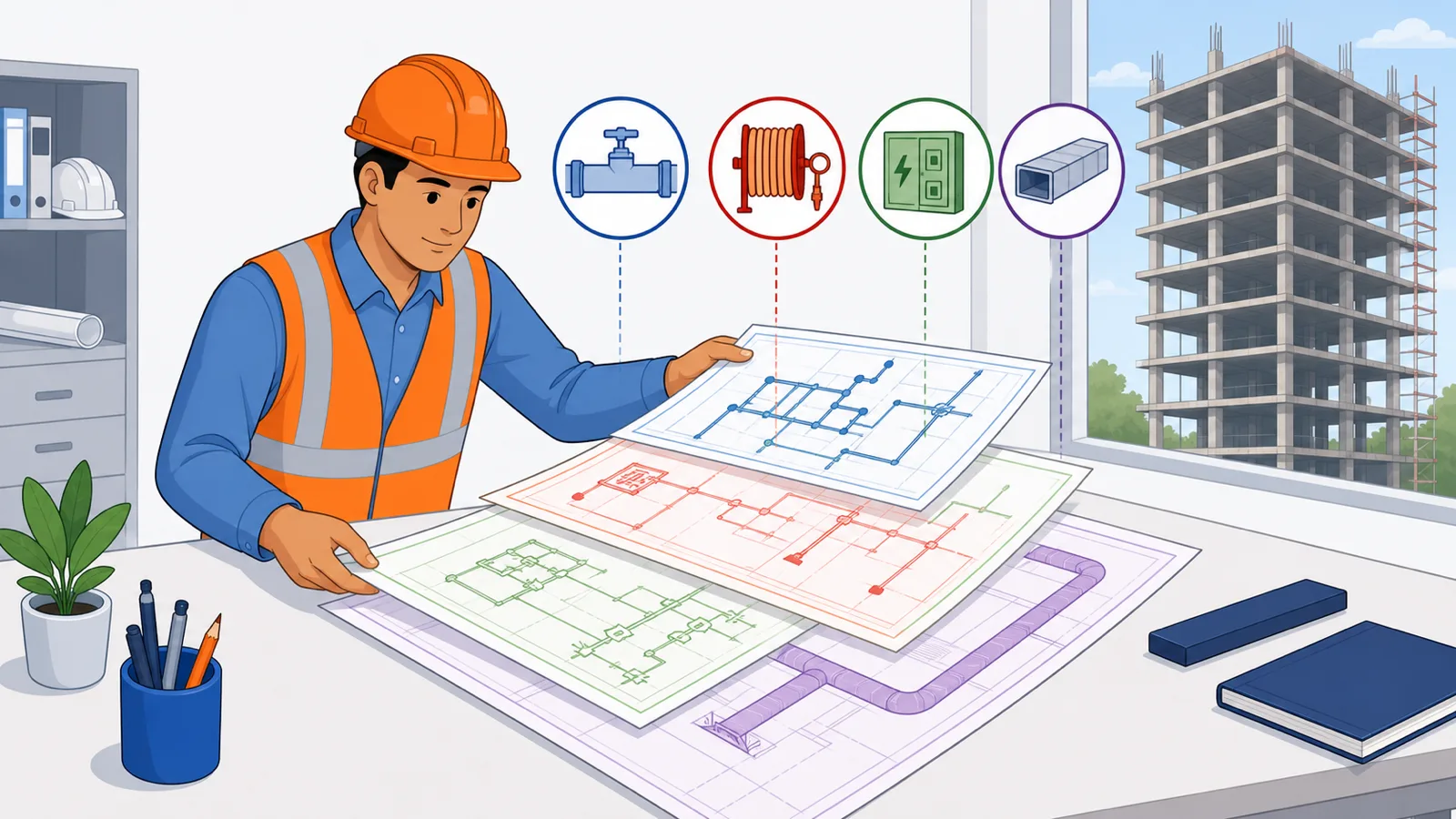
The slab is cast, the blockwork is up, the plaster gang has started — and then the plumbing contractor arrives with a cutter and opens a chase through your finished wall, while the electrician's helper hammers a hole beside a beam for a conduit that "was always going there." On most Indian sites, the services drawings arrive last, get read least, and cause the most rework. Every hole cut into hardened concrete, every AC drain that ponds because nobody checked its slope, every DB that ends up behind a door — all of it was visible on paper, on sheets the civil team never opened.
This module teaches you to open them. Not to design services — that is the MEP consultant's job — but to read the sheets well enough to check quantities, coordinate trades, and catch clashes before casting day. This first lesson maps the territory: what the four services families are, how each set is organised, and how to use the one page that unlocks all the others — the legend.
Four services, one repeating skeleton
MEP stands for mechanical, electrical and plumbing, but on an Indian commercial or residential project the drawing set usually splits into four families, often from different consultants and executed by different specialist agencies:
| Family | What its sheets cover | Typical agency on site |
|---|---|---|
| Plumbing and sanitary | Domestic, flushing and hot water supply; soil, waste, vent and rainwater drainage | Plumbing thekedar / PHE contractor |
| Fire fighting | Hydrants, sprinklers, pump room, fire tanks, signage | Licensed fire agency (statutory NOC work) |
| Electrical | Substation, single line diagram, power and lighting layouts, cable schedules, earthing | Electrical contractor (licensed) |
| HVAC | Ducting, refrigerant and chilled-water piping, equipment, condensate drains | HVAC vendor |
The four families look different, but each set repeats the same internal skeleton — and once you see the skeleton, no MEP set is frightening again:
- Legend and general notes sheet — the dictionary for every symbol, line type and abbreviation the consultant uses.
- Floor-wise layout plans — where things run horizontally on each floor.
- A vertical-logic sheet — the riser diagram or schematic for plumbing and fire, the single line diagram (SLD) for electrical. It shows how floors connect vertically.
- Details and schedules — toilet enlargements, pump room details, cable schedules, fixture schedules.
The reading order matters: legend first, then the vertical-logic sheet, then the floor plan. A floor plan read without its legend is guesswork — the same triangle symbol can mean a floor trap on one consultant's sheets and a valve on another's.
Design drawings, GFC, and shop drawings
Services go through the same lifecycle you learned in the GFC and revisions module. The MEP consultant issues design and then GFC sheets; the executing contractor then produces shop drawings — his own detailed working drawings showing exact routing, supports and fabrication — which the consultant approves before work starts. On site, the approved shop drawing governs fabrication, and you will find notes on GFC plans that openly defer to it: the plan sheet we read in the next lesson routes an AC drain "as per shop drawing." If you are measuring or checking services work, always ask which drawing the agency is actually working from, and check its revision the way Module 5 taught you.
The legend sheet is the dictionary
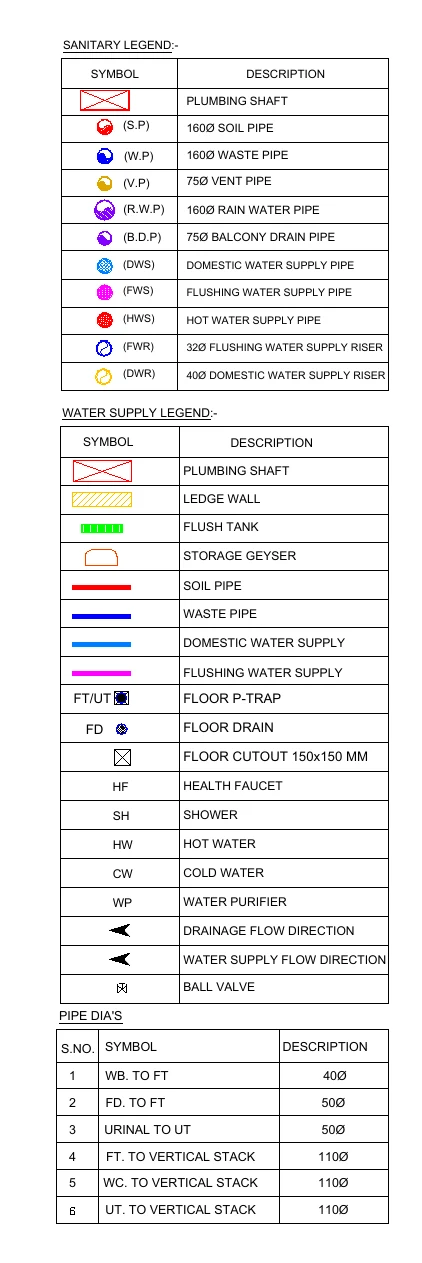
Below is the real legend and pipe-diameter block from the plumbing set of Project A, a nine-storey commercial tower. Spend five minutes with it and you can read every plumbing sheet in that building.
How to read this
- Start at the SANITARY LEGEND table: symbols on the left, descriptions on the right. The red crossed rectangle is the plumbing shaft — you will meet it on every floor plan in the set.
- Read the drainage family: (S.P) 160Ø soil pipe, (W.P) 160Ø waste pipe, (V.P) 75Ø vent pipe, (R.W.P) 160Ø rain water pipe and (B.D.P) 75Ø balcony drain pipe — five separate vertical stacks.
- Read the supply family: DWS domestic, FWS flushing and HWS hot water supply pipes, plus two sized risers — (FWR) 32Ø flushing and (DWR) 40Ø domestic water supply riser.
- The WATER SUPPLY LEGEND below maps line styles and colours for the plans — soil, waste, domestic and flushing lines each get their own — and tags like FT/UT floor P-trap, FD floor drain, HF health faucet, ball valve and the 150x150 mm floor cutout.
- Finish at the PIPE DIA'S table: WB to FT 40Ø, FD to FT 50Ø, urinal to UT 50Ø, and every trap, WC and urinal trap connecting to the vertical stack at 110Ø. These are the diameters branch work should be billed at.
Three things deserve a closer look.
First, drainage is split into separate stacks. This project runs a two-pipe drainage system: a 160Ø soil pipe (S.P) for WC discharge, a separate 160Ø waste pipe (W.P) for wash water from basins and floor drains, and a 75Ø vent pipe (V.P) whose only job is to let air in and out so that trap water seals are not sucked dry. Rainwater gets its own 160Ø stack (R.W.P), and balconies drain through a 75Ø balcony drain pipe (B.D.P). Five different vertical pipes, five different abbreviations — and on the floor plans, five line styles that the legend's second table maps to colours and patterns.
Second, water supply is also split. DWS is domestic water supply, FWS is flushing water supply, HWS is hot water. Flushing water running as a separate service is standard in commercial towers where treated or recycled water feeds the flush tanks — which is why the legend lists two separately sized risers: a 40Ø domestic water riser (DWR) and a 32Ø flushing water riser (FWR). On site this means two parallel pipe networks that must never be cross-connected; a plumber who tees a drinking-water point off the flushing line has created a health hazard that no walkthrough will spot later.
Third, the pipe-dia table fixes connection sizes. The bottom table is a small contract in itself: wash basin to floor trap 40Ø, floor drain to floor trap 50Ø, urinal to urinal trap 50Ø, and every trap and WC connecting to the vertical stack at 110Ø. When the plumbing bill arrives, these are the diameters each connection should be measured at — not the 160Ø of the stack.
Worked example: pricing the branch, not the stack
Here is the money angle, because in a QS course every symbol should cash out somewhere. Take one office-floor toilet block on Project A: 4 WCs, 3 wash basins, 2 urinals, 2 floor drains. Using the pipe-dia table:
| Connection | Count | Dia per table |
|---|---|---|
| WC to vertical stack | 4 | 110Ø |
| Wash basin to floor trap | 3 | 40Ø |
| Floor drain to floor trap | 2 | 50Ø |
| Urinal to urinal trap | 2 | 50Ø |
| Floor trap / urinal trap to stack | 4 | 110Ø |
Suppose the horizontal branch drainage on this floor measures 35 m, almost all of it 110Ø. Now take two illustrative installed rates — say Rs. 280 per metre for 110Ø SWR pipework and Rs. 450 per metre for 160Ø (illustrative figures for the arithmetic; always use your own BOQ rates and current city quotations). A contractor who measures the whole branch run "at stack size, 160Ø, to match the vertical" bills 35 x 450 = Rs. 15,750 instead of 35 x 280 = Rs. 9,800 — an excess of Rs. 5,950 on one floor. Across nine office floors that is roughly Rs. 53,550 of over-billing that the legend's little table lets you strike off in one sitting. This is the recurring promise of this course: the drawing is your defence, and it usually pays for the time spent reading it within one bill cycle. The same discipline applies when the bill goes the other way — the common BOQ mistakes lesson in the QS course shows how mis-described items leak money in both directions.
Where the codes sit
You do not need to design to these codes, but you should know which shelf they sit on. Plumbing design in India is governed by NBC 2016 Part 9 (Plumbing Services), which sizes supply and drainage pipes by the fixture-unit method — you will meet fixture units on a real riser diagram in the next lesson. Fire-fighting provisions come from NBC Part 4 (Fire and Life Safety) plus the state fire authority's NOC conditions, and electrical installations follow the NBC's electrical services part along with IS wiring and earthing standards. When a services drawing and a code seem to disagree, raise it as a question through an RFI — never resolve it silently on site.
Common mistakes
- Reading a services plan without its legend sheet. Symbols are consultant-specific. The same abbreviation FT can mean floor trap on one project and fire tank on another set of sheets.
- Assuming the architectural plan shows services. It shows fixtures — a WC, a basin — but not the pipes behind them. Only the MEP layouts show routing, and only the riser or SLD shows vertical logic.
- Ignoring "as per shop drawing" notes. They tell you the GFC sheet is deliberately incomplete at that spot; measuring or executing from it alone is building on a placeholder.
- Treating fire sheets as just more plumbing. Fire work is statutory, inspected, and executed by a licensed agency; a plumbing-style improvisation on a hydrant line can hold up the building's occupancy certificate.
- Letting each agency read only its own set. The clashes live between the sets — which is exactly where this module is heading.
What is next
You now know the skeleton of a services set and can decode the legend of a real one. The next lesson takes the two most important plumbing sheets — the floor plan and the riser schematic — and teaches the core skill of this module: reading them as a pair, because each one is honest about something the other hides.
Key takeaways
- An MEP set splits into plumbing, fire, electrical and HVAC families, but every family repeats the same skeleton: legend, floor layouts, a vertical-logic sheet, and details with schedules.
- Always read the legend sheet first — symbols and abbreviations are consultant-specific, and the same mark can mean different things on different projects.
- Project A runs two-pipe drainage: separate soil, waste and vent stacks, plus dedicated rainwater and balcony drain pipes, each with its own size fixed in the legend.
- Separate domestic and flushing water networks are standard in commercial towers; they must never be cross-connected on site.
- The pipe-dia table fixes connection sizes — wash basin to trap 40Ø, floor drain to trap 50Ø, trap and WC to stack 110Ø — and is your defence against branch work billed at stack rates.
- GFC services sheets often defer to approved shop drawings; always confirm which drawing and which revision the executing agency is working from.
Verify on site
- Collect the legend and general notes sheet for every services discipline before checking any layout.
- Confirm the revision of each services sheet against the drawing register before measuring or executing from it.
- Verify delivered pipe diameters and material against the legend and pipe-dia table, not against the plumber's memory.
- Trace one domestic and one flushing line on site to confirm the two networks are not cross-connected.
- Ask each MEP agency which approved shop drawings they are working from, and file copies in the site office.
- Check branch drainage measurements in bills against the pipe-dia table diameters before certifying.
Check your understanding
5 questions. Answering them marks this lesson complete — results stay on your device.
Want the free certificate?
The whole course is free and open — no signup needed to learn. Enter your details only if you want us to track your progress on this device and issue a named certificate after the final assessment.