Electrical Layouts and the Single Line Diagram
Lesson 27 of 32 · 8 min read
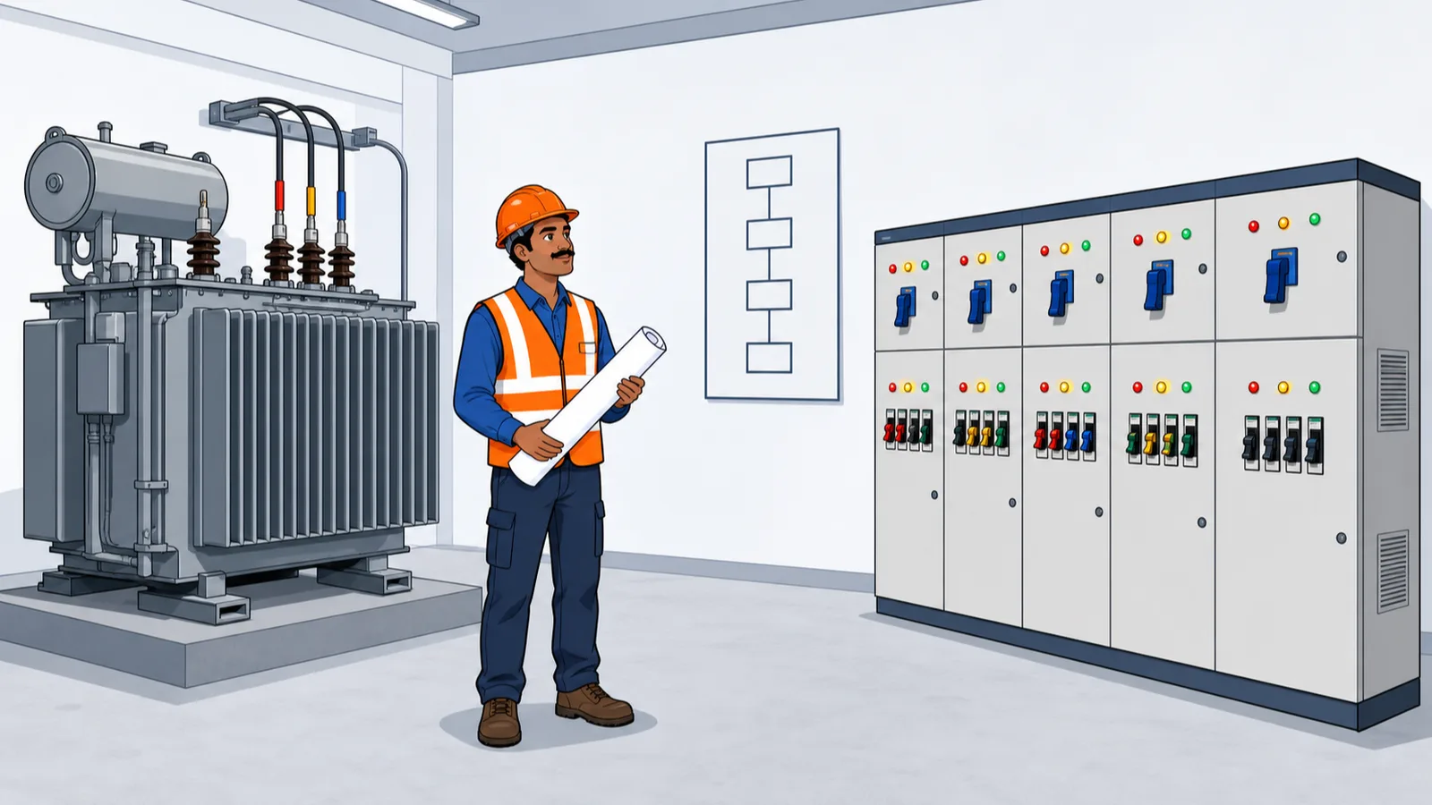
Ask a civil site engineer to check a plumbing bill and he will grumble but manage. Hand him the electrical single line diagram and he hands it straight back — too many symbols, too many abbreviations, clearly somebody else's problem. Then the electrical contractor's bill arrives with lakhs of rupees of cable, panels and breakers on it, and "somebody else" turns out to be nobody. The SLD is not a specialist's secret. It is the electrical set's version of the riser schematic you read in the last lesson: a logic diagram, not to scale, read top-down from the grid to the last light point. This lesson walks the real SLD of Project A, the nine-storey commercial tower, in two halves — the high-tension incoming chain and the low-tension distribution bus.
What "single line" means
A building's power flows through three phases (plus neutral), so every real circuit is three or four conductors. Drawing all of them would triple the linework and add nothing, so the SLD draws one line to represent the whole group of conductors, with symbols hung on it for every device the power passes through. Read it like a river: source at the top, distribution at the bottom, and every symbol on the way is something the current must flow through — a breaker, a meter, a transformer.
The vocabulary you need is short: HT/LT — high tension (11,000 V here) and low tension (415 V three-phase / 240 V single-phase); kVA vs kW — apparent power vs real power, related by the power factor (kW = kVA x pf); and the breaker family — ACB (air circuit breaker, the big ones), MCCB (moulded case circuit breaker, the middle weight), MCB (miniature circuit breaker, the final circuits), with TP/TPN/4P telling you how many poles the breaker switches.
The HT incoming chain, top-down
How to read this
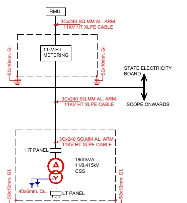
- Start at the top box: RMU — the ring main unit, the utility's 11 kV switching point where the project taps the network.
- Follow the single line down into the dashed enclosure labelled 11kV HT METERING — the DISCOM's meter lives on the HT side in its own chamber.
- Read the repeated red cable tag word by word: 3Cx240 SQ.MM AL. ARM. 11KV HT XLPE CABLE — 3 cores, 240 sq.mm each, aluminium, armoured, 11 kV grade, XLPE insulated. Every cable bill is checked against this grammar.
- Find the horizontal double arrow between STATE ELECTRICITY BOARD and SCOPE ONWARDS: the contract boundary. Upstream is the utility's cost; everything downstream is the project's.
- The lower dashed enclosure is the CSS — a compact substation with HT panel, the 1600 kVA 11/0.415 kV transformer (note the winding symbols) and LT panel in one unit.
- Read the margin tags 50x10mm GI and 40x6mm Cu — the earthing strips every enclosure connects to. Earthing is a measurable BOQ item hiding at the sheet edge.
Start at the top box: RMU, the ring main unit — the utility's 11 kV switching point where the project connects to the distribution network. The single line drops from it through a dashed enclosure labelled 11kV HT METERING: the DISCOM's energy meter sits on the HT side, inside its own chamber.
Now read the cable tag that repeats along the chain, because cable tags are half of all electrical reading: 3Cx240 SQ.MM AL. ARM. 11KV HT XLPE CABLE. Unpack it word by word: 3 cores; 240 sq.mm conductor cross-section per core; aluminium conductor; armoured (a steel layer for mechanical protection, which also earths the run); 11 kV voltage grade; XLPE insulation. Every cable in the electrical BOQ is described in exactly this grammar, and checking a cable bill starts with matching this tag, word by word, against what was actually laid.
Between the metering chamber and the next enclosure sits the most contractual mark on the sheet: a horizontal double arrow with STATE ELECTRICITY BOARD on one side and SCOPE ONWARDS on the other. That arrow is a money boundary. Everything upstream belongs to the utility; everything downstream — cable, civil work, maintenance — is the project's cost. When a dispute erupts over who pays for a cable trench or a chamber, this arrow on a signed drawing settles it. Note it the way you would note a property boundary.
The line then enters the main dashed enclosure: the CSS, a compact substation, containing an HT panel, the transformer, and an LT panel in one factory-built unit. The transformer is the heart of the sheet: 1600 kVA, 11/0.415 kV — it steps 11,000 volts down to the 415 V three-phase the building actually uses. Along both margins run the earthing tags — 50x10mm GI strip and 40x6mm Cu — the strips every enclosure body connects to. Earthing runs are measurable BOQ items too; they hide in the margins of the SLD.
From kVA to amperes: the one calculation you need
The LT sheet is sized in amperes, the transformer in kVA. One formula connects them — current in a three-phase system:
I = kVA x 1000 / (1.732 x V)
For the 1600 kVA transformer at 415 V: I = 1,600,000 / (1.732 x 415) = 1,600,000 / 718.8 = 2,226 A. Hold that number and look at the next excerpt.
The LT bus and its feeders
How to read this
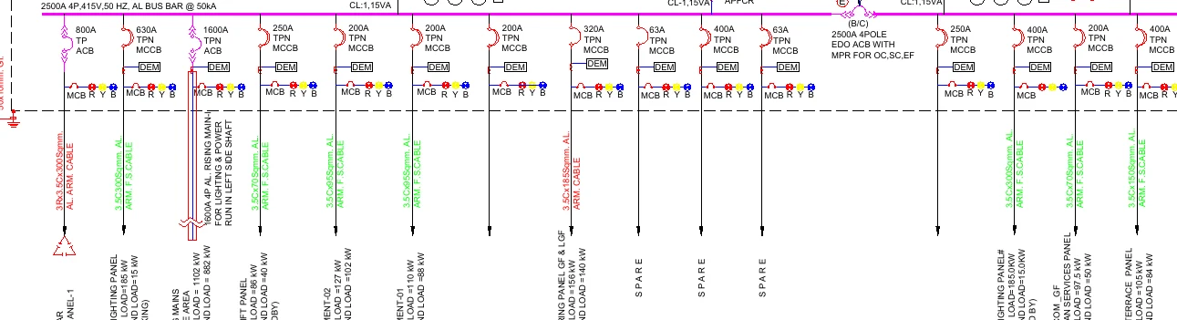
- Read the busbar label across the top: 2500A 4P, 415V, 50 HZ, AL BUS BAR @ 50kA — the ampacity, poles, voltage and fault rating of the whole panel in one line.
- Pick any vertical drop: the breaker comes first — 800A TP ACB, 630A TPN MCCB, 1600A TPN ACB — then a DEM meter box and R-Y-B phase indicating lamps.
- Below the components, read the cable tag (for example 3.5Cx185Sqmm AL ARM. CABLE) and the load name with two numbers — connected LOAD and DEMAND LOAD in kW.
- Find the 1600 A rising-main feeder and its routing note: the 4P aluminium rising main for lighting and power runs in the left side shaft — a builders-work requirement that must exist in the structure.
- Note the SPARE feeders (63 A, 400 A) — empty ways for future loads that still appear in the panel BOQ — and the central 2500A 4-pole EDO ACB with MPR for OC, SC and EF protection tying the bus.
The long magenta band across the top is the main busbar of the LT panel, and its label is a specification in one line: 2500A 4P, 415V, 50 HZ, AL BUS BAR @ 50kA. A 2,500-ampere, four-pole aluminium busbar rated to survive a 50,000-ampere fault. Now the transformer calculation pays off: full-load current is 2,226 A, and the bus is the next standard size up — 2,500 A. The drawing suddenly has internal logic: nothing on a good SLD is arbitrary, and you can audit it with one multiplication.
Every vertical drop from the bus is a feeder, and each one repeats the same anatomy, which the figure below dissects:
- The breaker first: 800A TP ACB, 630A TPN MCCB, 1600A TPN ACB, and so on — the protective device rated for that feeder's load.
- Metering and indication: a DEM (digital energy meter) box and R-Y-B phase indicating lamps on each feeder.
- The cable tag in the same grammar as the HT side — 3.5Cx185Sqmm AL ARM. CABLE and its siblings (3.5 core: three phases plus a reduced neutral).
- The load name with two numbers: for the rising main, LOAD = 1102 kW and DEMAND LOAD = 882 kW; for the lift panel, LOAD = 66 kW and DEMAND LOAD = 40 kW.
Those two numbers teach the most important idea in building electrical design: connected load vs demand load. Connected load is everything that could draw power if switched on at once; demand load applies a diversity factor because it never is. Here the rising main carries a diversity of 882 / 1102 = 0.80, and the lifts 40 / 66 = about 0.61 (lifts rarely all run together). Feeders, cables and the transformer are sized on demand, not connected load. When you check the drawing: the rising main's demand of 882 kW at, say, 0.9 power factor draws I = 882,000 / (1.732 x 415 x 0.9) = 882,000 / 647 = 1,363 A — and its breaker is a 1,600 A ACB. Again the next size up; again the sheet audits itself.
Three more details reward a careful reader. The 1600 A rising-main feeder carries a routing note — the rising main for lighting and power is to run in the left side shaft — a builders-work instruction that must match a real structural shaft (remember it in Lesson 4). Several feeders are labelled SPARE (63 A, 400 A): empty breakers for future loads, which also appear in the BOQ, so do not strike them off a bill as "not installed" without checking. And mid-bus sits a 2500A 4-pole EDO ACB with MPR for OC, SC, EF — an electrically-drawout air circuit breaker whose microprocessor release protects against overcurrent, short circuit and earth fault; on this panel it works as the bus coupler / incomer-class device tying the bus sections.
Where the money hides
An electrical bill is mostly cable metres, panel line-items and breaker counts — and every one of them is on or behind this sheet. The feeder list is a checklist for the panel bill: count the breakers by rating, match cable tags item by item. Cable lengths come from the layout plans and the cable schedule, and reconciling drawing quantities against the BOQ is exactly the drill in the drawing-vs-bill lesson of Module 7 — where you will meet this same panel's cable-selection table, including the parallel runs a 2,226 A feeder demands. On the statutory side, the HT metering chamber, transformer capacity and sanctioned load are what the DISCOM and the electrical inspector approve; a mismatch between the SLD and the sanctioned load surfaces at the worst possible time — energisation.
Common mistakes
- Treating the SLD as to-scale or positional. Like the riser schematic, it is pure logic. The physical panel room layout is a different drawing.
- Reading one number of a cable tag. 3.5Cx185 AL and 3.5Cx185 Cu differ hugely in price; armoured vs unarmoured likewise. Match the whole tag.
- Confusing kVA with kW. The transformer is 1600 kVA, not 1600 kW; multiply by power factor before comparing with load sums.
- Sizing checks against connected load. Feeders are sized on demand load; flagging a 1600 A breaker as "too small for 1102 kW connected" wastes everyone's afternoon.
- Ignoring the scope arrow. Who pays for what at the utility boundary is drawn, not negotiable after the fact.
What is next
You can now read both wet and electrical services vertically. The final lesson puts the services back onto the structure — literally overlaying one drawing on another — to catch the sleeves, cutouts and khurras that clash with beams while the fix still costs a sheet of plywood, not a diamond core cutter.
Key takeaways
- An SLD is the electrical riser diagram: one drawn line stands for all phases, read top-down from grid to final circuit, and it is never to scale.
- Cable tags follow a fixed grammar — cores x size, conductor material, armouring, voltage grade, insulation — and bills are checked against the whole tag, not one number.
- The scope-demarcation arrow between the utility and the project is a contract boundary drawn on the sheet; it decides who pays at the interface.
- Convert kVA to amperes with I = kVA x 1000 / (1.732 x V): Project A's 1600 kVA transformer gives 2,226 A, matching its 2500 A busbar — a good SLD audits itself.
- Connected load and demand load differ by the diversity factor (882/1102 = 0.80 on the rising main); equipment is sized on demand load.
- The breaker hierarchy runs ACB, MCCB, MCB from main panel to final circuits; spare feeders are real BOQ items even though nothing hangs on them yet.
Verify on site
- Match the transformer rating, busbar rating and incomer breaker on the nameplates against the SLD before energisation checks.
- Verify each installed feeder breaker's type and rating against the SLD feeder list, including spares.
- Check laid cable tags (printed on the sheath) word by word against the SLD and cable schedule before certifying cable bills.
- Confirm the rising main is routed in the shaft named on the SLD and that the shaft exists as builders-work.
- Trace and measure earthing strips (GI and copper) against the margins of the SLD and the earthing layout.
- Reconcile the DISCOM sanctioned load and metering arrangement with the SLD before applying for connection.
Check your understanding
5 questions. Answering them marks this lesson complete — results stay on your device.
Want the free certificate?
The whole course is free and open — no signup needed to learn. Enter your details only if you want us to track your progress on this device and issue a named certificate after the final assessment.