Reading Plumbing and Drainage Drawings
Lesson 26 of 32 · 8 min read
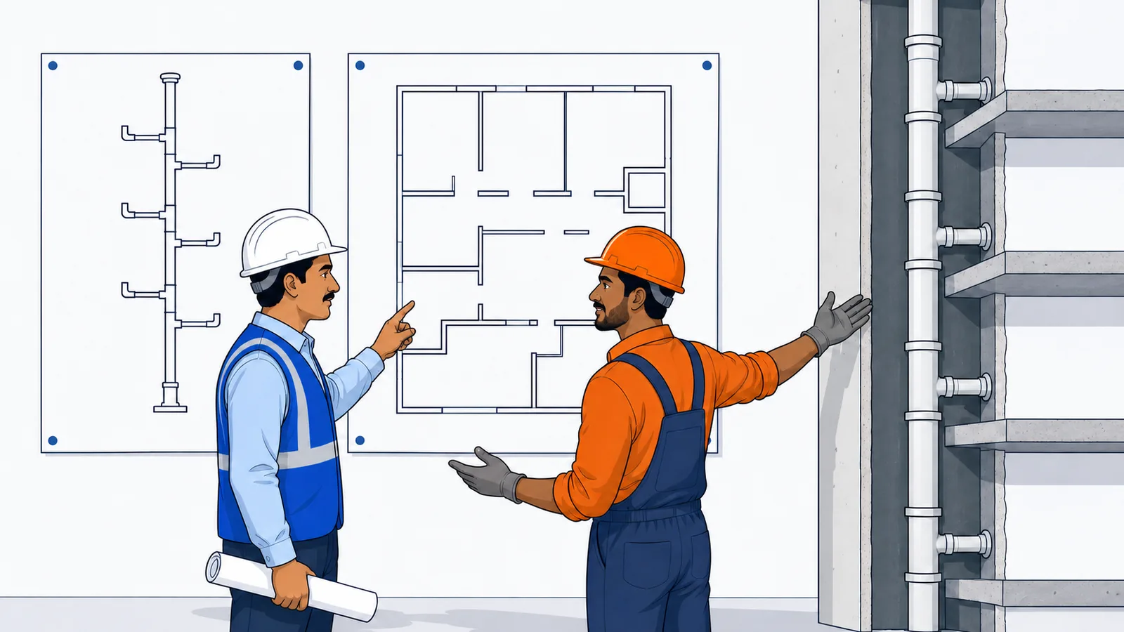
Stand in a corridor of a nine-storey tower and look at the plumbing shaft: a 600 x 300 hole in the wall with four pipes disappearing up and down into darkness. Now the plumbing contractor hands you a bill for 32Ø riser pipe, 25Ø riser pipe and 20Ø riser pipe, all in that one shaft, all in lengths you cannot see. Which drawing do you check it against? Not the floor plan — it shows the shaft as a rectangle and tells you nothing about what happens above or below this floor. You need the sheet most civil engineers have never opened: the riser schematic.
This lesson teaches the schematic-vs-plan pair, using the real domestic water riser diagram and a matching floor-plan crop from Project A, a nine-storey commercial tower. The skill transfers directly to drainage stacks, fire risers and electrical rising mains — every vertical service has a schematic somewhere in its set.
Two views, two kinds of truth
A floor plan is geometrically true: distances, positions, wall thicknesses are to scale, and you can locate the shaft to the millimetre. But it is vertically blind — it shows one horizontal slice of the building.
A schematic (riser diagram) is the opposite. It is a logic diagram: floors become horizontal lines, risers become vertical lines, and every connection is shown truthfully — but nothing is to scale. A branch drawn 40 mm long on the schematic might run 12 m on site, and two risers drawn side by side might sit in shafts at opposite ends of the corridor.
The rule that follows: take positions and horizontal lengths from the plan; take connectivity, floor-wise sizes and vertical logic from the schematic. Any measurement scaled off a schematic is fiction — and remember from Module 1 that the general notes usually ban scaling from any drawing at all; dimensions govern.
Reading a real riser schematic
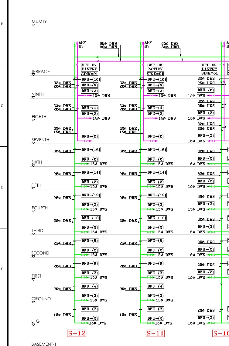
How to read this
- Read the floor names down the left margin — MUMTY, TERRACE, NINTH ... GROUND, L.G, BASEMENT-1. Each horizontal line is a floor level, not a wall: this sheet is a logic diagram, not a plan.
- Each vertical column is one riser, tagged in a red box at the bottom: S-12, S-11, S-10. The same tags appear beside plumbing shafts on the floor plans — that tag is how you match diagram to building.
- At terrace level, find the 65Ø and 80Ø DWS header feeding the risers from the tank, with ARV and BV valve tags at the riser heads, and boxed labels like OFF-07 PANTRY SINK=01 naming what each riser serves.
- Follow one riser down: at every floor a 15Ø DWS branch taps off with a boxed DFU-(2) — two fixture units for that floor's pantry connection.
- Now read the boxed counts on the stack from the bottom up — DFU-(2), (4), (6) ... DFU-(16) — growing by 2 per floor, and watch the stack diameter step 15Ø, 20Ø, 25Ø, 32Ø as the cumulative count grows. That stepping is what you bill dia-wise.
- Note the parallel coloured lines sharing each riser column — separate lines serving different floor zones share one shaft. The labels tell you which is which; never assume one shaft means one pipe.
This is the domestic water supply (DWS) schematic for part of Project A. The floor names run down the left margin — MUMTY and TERRACE at top, down through NINTH to GROUND, L.G and BASEMENT-1. Each vertical column is one riser, and each carries a tag in a red box at the bottom: S-12, S-11, S-10. Those tags are the hinge between sheets — the same tag appears beside a shaft on the floor plans, which is how you match a vertical line on this diagram to a physical hole in the building.
Now read one riser from the top. At terrace level a header pipe tagged 65Ø and 80Ø DWS feeds the risers from the overhead tank — the largest pipes in the picture, because up here the pipe serves everything below. Valve tags ARV and BV sit at the riser heads: an air release valve to bleed trapped air, and an isolation valve so one riser can be shut without draining the building. Boxed labels like OFF-07 PANTRY SINK=01 tell you exactly what each riser exists to serve — one pantry sink per office, floor after floor.
At every floor, a 15Ø DWS branch taps off to serve that floor's pantry, and beside each tap sits a boxed count: DFU-(2) — two fixture units for that branch. Fixture units are the currency of plumbing design: NBC 2016 Part 9 sizes water supply and drainage pipes by fixture-unit tables rather than by adding up raw flows, because not every tap runs at once. (Strictly, supply-side counts are water supply fixture units; this consultant labels them DFU on the sheet — read the label, keep the concept.)
Here is the elegant part. Follow the boxed counts on the stack itself, reading upward from the bottom: DFU-(2), DFU-(4), DFU-(6), DFU-(8), DFU-(10), DFU-(12), DFU-(14), DFU-(16). The count grows by 2 at every floor, because this is a down-feed riser: the segment above any floor must carry water for that floor and every floor below it. And as the count grows, the pipe diameter steps with it — the same stack reads 15Ø at its lowest segment, then 20Ø, then 25Ø, then 32Ø near the top. On this project the bands work out to: 2 fixture units on 15Ø, 4 to 6 on 20Ø, 8 to 14 on 25Ø, and 16 on 32Ø. You do not need to reproduce the consultant's sizing table — you need to recognise the pattern, because it is exactly what you will bill and check.
One honesty note: on the real sheet each riser column contains more than one vertical line, drawn in different colours — high-rise buildings split supply into pressure zones, and parallel risers serving different floor bands share one shaft. The labels and DFU boxes tell you which line is which. Never assume one shaft means one pipe.
The plan half of the pair
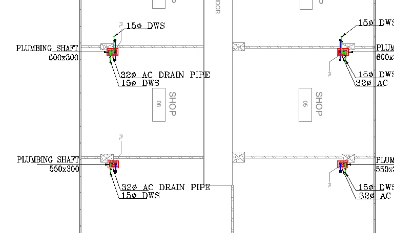
How to read this
- Find the red crossed rectangles on the wall line — the plumbing-shaft symbol from the legend in Lesson 1. Callouts give their sizes: PLUMBING SHAFT 600x300 and 550x300.
- From each shaft, trace the 15Ø DWS tap entering the shop unit — this is the plan-end of the riser branch you read on the schematic.
- Read the 32Ø AC DRAIN PIPE callout: the air-conditioning condensate drain drops into the same shaft alongside the water supply.
- The room tags (SHOP 05, SHOP 08) and the corridor between them tell you which tenant each shaft serves.
- Notice what this plan cannot tell you: the riser diameter at this level, or where it changes above and below. That information lives only on the schematic — which is why the two sheets are read as a pair.
This crop is from a typical floor plan of the same building — the shop level. The red crossed rectangles on the wall line are the legend's plumbing-shaft symbol from Lesson 1, here with sizes called out: PLUMBING SHAFT 600x300 on one pair, 550x300 on another. From each shaft, a 15Ø DWS tap enters the unit — this is the plan-end of the very branch you just read on the schematic. A second callout marks a 32Ø AC DRAIN PIPE dropping condensate into the same shaft, and the room tags (SHOP 05, SHOP 08) tell you which tenant each shaft serves.
Notice what each sheet refuses to tell you. The plan gives you shaft positions, shaft sizes and which unit each tap serves — but not what diameter the riser is at this level, or where it changes. The schematic gives you diameters, fixture units and connections — but could not locate a shaft if you paid it. Reading plumbing drawings is the act of shuttling between the two with a finger on each.
Worked example: a dia-wise riser takeoff
Time to cash the skill. Suppose a down-feed riser like the ones above serves eight floors, two fixture units per floor, with the same sizing bands, and the structure's floor-to-floor height is 3.5 m (read your project's height from the sections — never assume it). The takeoff, floor by floor:
| Segment (above floor) | Cumulative fixture units | Dia | Length |
|---|---|---|---|
| Above 7th (from terrace header) | 16 | 32Ø | 3.5 m |
| Above 6th | 14 | 25Ø | 3.5 m |
| Above 5th | 12 | 25Ø | 3.5 m |
| Above 4th | 10 | 25Ø | 3.5 m |
| Above 3rd | 8 | 25Ø | 3.5 m |
| Above 2nd | 6 | 20Ø | 3.5 m |
| Above 1st | 4 | 20Ø | 3.5 m |
| Above Ground | 2 | 15Ø | 3.5 m |
Dia-wise totals: 32Ø — 3.5 m, 25Ø — 14 m, 20Ø — 7 m, 15Ø — 3.5 m (28 m of vertical pipe in all). Now price it with illustrative installed rates of Rs. 350 per metre for 32Ø, Rs. 250 for 25Ø, Rs. 180 for 20Ø and Rs. 120 for 15Ø (illustrative only — use your BOQ). The correct bill is 3.5x350 + 14x250 + 7x180 + 3.5x120 = 1,225 + 3,500 + 1,260 + 420 = Rs. 6,405. A bill that measures the whole riser "at 32Ø, as per top size" claims 28 x 350 = Rs. 9,800 — an excess of Rs. 3,395, about 53 percent over the correct amount, on a single riser. The excerpt's sheet alone tags risers S-10, S-11 and S-12; a tower with a dozen such risers leaks roughly Rs. 40,000 on this one item if nobody reads the schematic. The riser diagram is not a designer's decoration; it is the measurement sheet for every vertical metre of pipe in the building.
Common mistakes
- Scaling any length off the schematic. It is not to scale, ever. Vertical lengths come from floor-to-floor heights on sections; horizontal runs come from the plan.
- Billing the riser at one diameter. As the worked example shows, down-feed and drainage stacks both change size along their height. Demand a dia-wise measurement.
- Assuming the branch matches the riser size. The branch here is 15Ø off a 32Ø stack. Branch and stack are separate BOQ items.
- Ignoring zone splits. Two parallel lines in one shaft serving different floor bands is normal in tall buildings; billing both as full-height doubles the quantity.
- Losing the riser tag. S-11 on the schematic must match S-11 beside a shaft on the plan. If tags do not reconcile between sheets, raise it — Module 7 is full of what happens when they silently do not.
What is next
You can now read the wet services vertically and horizontally. The next lesson applies the same schematic mindset to the sheet electrical engineers treat as their bible — the single line diagram — and shows that reading one is no harder than following this riser down from the tank.
Key takeaways
- A floor plan is geometrically true but vertically blind; a riser schematic is true about connections and sizes but never to scale — read them as a pair.
- Riser tags (S-10, S-11, S-12 on Project A) are the hinge between the schematic and the plan: the same tag marks the vertical line on one sheet and the shaft on the other.
- Fixture units are the currency of pipe sizing under NBC 2016 Part 9; on a down-feed riser the cumulative count grows by each floor's fixture units toward the top.
- Riser diameters step with cumulative load — on Project A from 15Ø at the lowest segment to 32Ø near the terrace — so risers must be measured and billed dia-wise, never at one size.
- Tall buildings run parallel risers for different pressure zones in one shaft; billing both as full-height doubles the quantity.
- Never scale lengths off a schematic: vertical lengths come from floor-to-floor heights on sections, horizontal runs from the plan.
Verify on site
- Match every riser tag on the schematic to a physical shaft on the floor plan before certifying any vertical pipe measurement.
- Check the plumbing bill measures risers dia-wise, with lengths derived from actual floor-to-floor heights.
- Open a shaft on one floor and verify the number of pipes matches the schematic — including zone risers.
- Confirm each floor's branch tap diameter on site against the schematic before it is concealed.
- Verify isolation and air-release valves exist at riser heads as drawn, and are accessible for maintenance.
- Photograph shaft internals floor-wise before they are closed; the photos are your measurement record in a dispute.
Check your understanding
5 questions. Answering them marks this lesson complete — results stay on your device.
Want the free certificate?
The whole course is free and open — no signup needed to learn. Enter your details only if you want us to track your progress on this device and issue a named certificate after the final assessment.