Overlaying MEP on Structure: Spotting Clashes on Paper
Lesson 28 of 32 · 7 min read
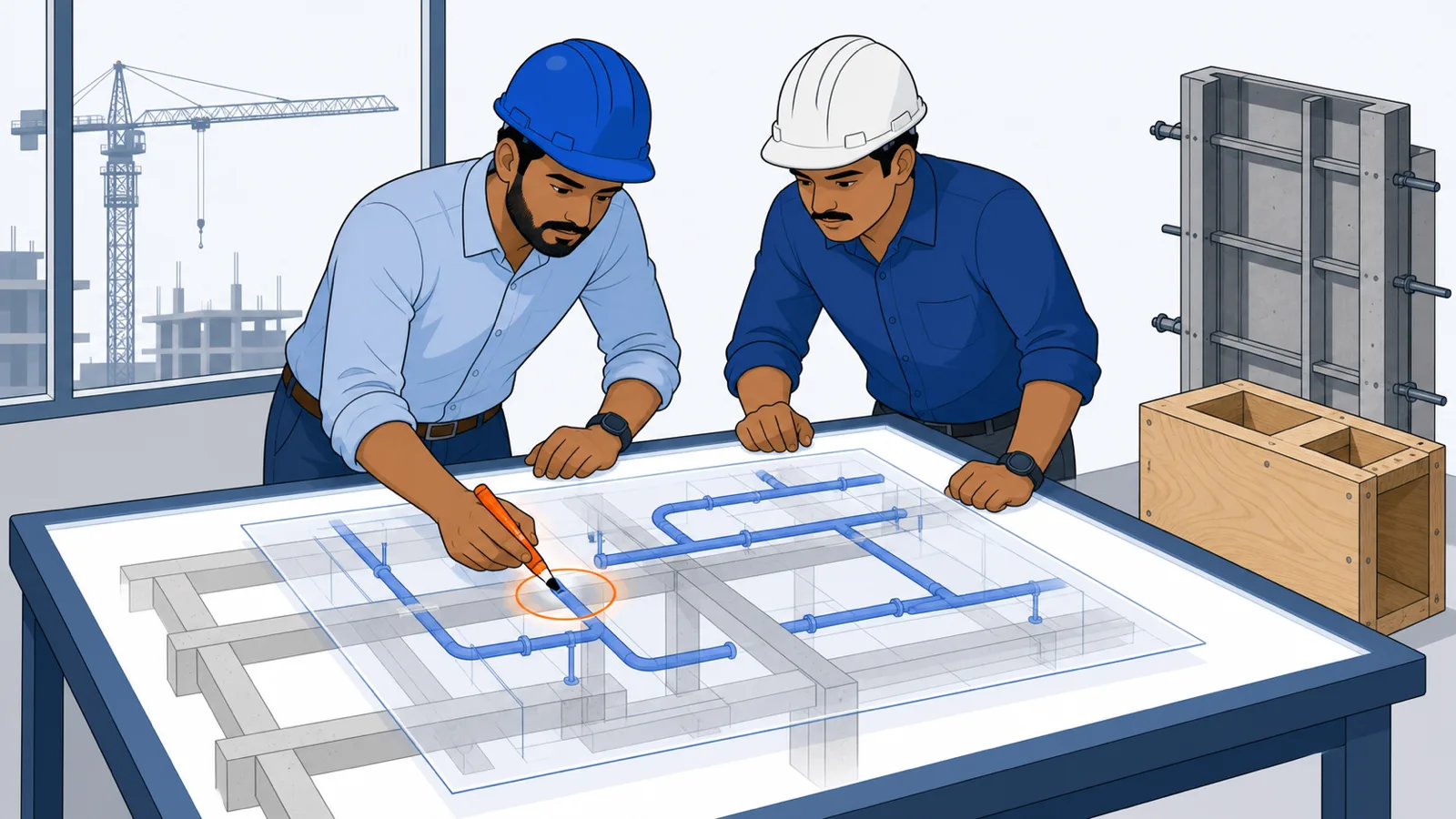
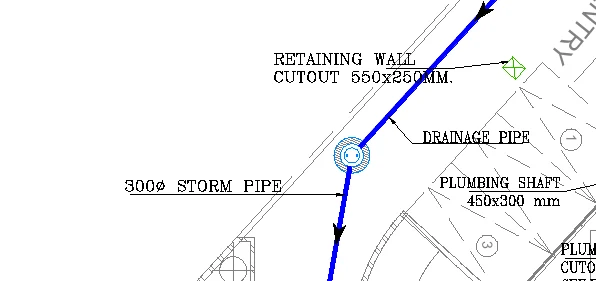
On the ground-floor plumbing layout of Project A, the nine-storey commercial tower, there is a small callout that is worth more than most sheets in the set: RETAINING WALL CUTOUT 550x250MM. It marks a hole — a builders-work opening that must exist in a reinforced concrete retaining wall so a drainage line can leave the building. Before the wall is cast, providing that hole costs a plywood box-out nailed into the shutter: a few hundred rupees and ten minutes of a carpenter's time. After the wall is cast, it costs diamond cutting or core drilling through mature RCC, cut rebar that worried the structural engineer, waterproofing repair on a water-retaining wall, an approval trail, and days of delay — realistically Rs. 25,000 to 50,000 all-in on a single opening (indicative mid-2026 figures; the exact number depends on wall thickness and access, but it is never small). Same hole. The only variable is when somebody read two drawings together.
That is this lesson: the paper overlay. BIM software finds clashes by loading every discipline's model into one space. On most Indian sites you will not have a federated model — but you have prints, a table, and the same principle: put the services drawing on the structural drawing for the same level and walk every point where they touch. It is the cheapest quality control in construction, and it is a reading skill, not a software skill.
The seed exercise: one cutout, two drawings
How to read this
- Read the boxed-out callout first: RETAINING WALL CUTOUT 550x250MM, with its leader pointing to where the heavy blue line crosses the hatched wall linework.
- The heavy blue line is tagged DRAINAGE PIPE; follow its flow arrows. A second label marks the 300Ø STORM PIPE on the same run.
- Find the PLUMBING SHAFT 450x300 mm callout — the vertical drop point the horizontal runs are heading for.
- The hatched linework the pipes cross is the retaining wall; the circled numbers are the sheet's wall or grid references.
- Now the overlay question: this opening is drawn on the plumbing layout — the wall is cast from the structural drawing. Unless the cutout reaches the RCC sheet or the shutter crew in writing before casting, the wall is cast solid and this becomes a diamond-cutting job.
Read the crop. The heavy blue line is tagged DRAINAGE PIPE; a second label marks a 300Ø STORM PIPE with its flow arrow; a PLUMBING SHAFT 450x300 mm callout sits nearby where the vertical services drop. The hatched linework the pipes cross is the retaining wall — and the callout names the opening the wall must be cast with: 550 x 250 mm.
Now the critical observation: this callout lives on the plumbing layout. The wall will be cast by the structural contractor, reading the structural drawing — and if the RCC sheet and the shutter carpenter never hear about this opening, the wall gets cast solid. The overlay question for every such callout is brutal and simple: does the drawing the casting crew is actually holding show this hole? If not, it goes into an RFI today, in writing, with both drawing numbers quoted — the discipline you built in the revisions module.
The overlay method, step by step
- Same level, current revisions. Pull the services layout and the structural (framing or wall) drawing for the same floor, and confirm both revisions against the drawing register — overlaying a superseded sheet finds imaginary clashes and misses real ones.
- Same scale. Prints must match (1:100 on 1:100). If one sheet is 1:150, rescale the print or work on a screen overlay — most PDF viewers can stack two drawings with transparency.
- Align the grids. Grid intersections are the shared skeleton of every discipline's sheets — line up A1 over A1, B4 over B4 (Module 2's setting-out skill doing coordination duty).
- Walk every crossing. Trace each pipe, duct, cable tray and shaft. Every place it meets a beam, wall, column or slab edge is a question: through a provided opening, below the soffit, or straight into concrete?
- Log and raise. Every conflict gets a cloud on your print, a line in a register, and an RFI before the pour — not a verbal mention in the evening meeting.
The clash gallery: what to look for
Sleeves and cutouts vs beams and walls. The Project A cutout above is the type specimen: services need holes, and holes must be cast in, not cut later. Check every wall the drainage crosses, every beam a sleeve is supposed to pierce. A sleeve through a beam is only ever acceptable where the structural consultant has detailed it — size, position along the span, and depth within the beam are all structural decisions. The rule on site: no opening in any RCC member without it appearing on a structural drawing or a written structural approval. A pipe-fitter's hammer drill does not know where the stirrups are.
Khurra and drain positions vs beam positions. A khurra is the dished depression at a terrace rainwater outlet — you met them on the terrace drainage plan in the architecture-vs-structure lesson. Every khurra needs a rainwater pipe dropping through the slab directly below it. Overlay the terrace drainage plan on the terrace framing plan: if a khurra or floor drain lands on or beside a beam, the drop pipe has nowhere to go — an offset bend buried in the slab is a future blockage, and a core cut through the beam is forbidden. The fix on paper is a two-minute move of the khurra; the fix after casting is an argument between three consultants.
Shaft continuity. The plumbing shafts from Lesson 2 and the electrical rising-main shaft from Lesson 3 (the SLD note said the 1600 A rising main runs in the left side shaft) must exist as real, continuous, stacked openings on every structural floor plan. One floor where the slab was cast solid across a shaft position converts the shaft into a series of core-cutting jobs.
Gravity pipes vs beam soffits. Drainage and condensate lines cannot climb. That 32Ø AC drain from Lesson 2 needs a continuous fall — commonly around 1:100 for small-bore drains (confirm the slope your project's notes specify) — and beams hang down into its path.
Worked example: the condensate drain that would not fit
A corridor run on a typical floor: an AC unit's 32Ø condensate drain must travel 24 m to reach the plumbing shaft. The services zone above the false ceiling is bounded by the beam soffits at 3,000 mm above FFL, and the ceiling is planned at 2,850 mm — a 150 mm service zone below the beams.
- Fall required at 1:100 over 24 m = 24,000 / 100 = 240 mm.
- Space available below beam soffit = 3,000 - 2,850 = 150 mm, less the pipe's own diameter and support clearance, roughly 110 mm usable.
- 240 mm needed vs 110 mm available: the drain does not fit. Drawn in elevation nothing looks wrong; only the overlay of run length, slope arithmetic and structure exposes it.
The paper fixes, in order of preference: shorten the run (a second shaft or a nearer stack), agree cast-in sleeves through two beams with the structural consultant before casting, or drop the ceiling in that corridor — an architect's decision, made calmly on paper. The site fix, discovered after ceiling framing starts, is usually a flat-run drain that ponds, grows slime, and drips through somebody's false ceiling every monsoon for the life of the building.
Who pays for the hole — the builders-work question
Openings, sleeves, chases and cutouts sit in a contractual no-man's-land called builders' work in connection with services, and every bill dispute about them ends at the drawings. Commonly (confirm against your own contract): openings shown on structural or builders-work drawings before casting are the civil contractor's work, measured or included in his rates; cutting done later because a services agency failed to give the opening in time lands on the services agency; and cutting because nobody coordinated lands on whoever cannot produce paper. Which is the point of this lesson's habit: the engineer who overlays the sheets, clouds the conflicts, and sends the RFI with drawing numbers is the one whose company is not funding the diamond cutter. Keep a one-page builders-work register — opening, size, level, drawing reference, status — and get it initialled before every major pour; it is a checklist before the pour and evidence after it.
Common mistakes
- Overlaying mismatched revisions. The clash you find may already be resolved — or a resolved sheet may hide a new one. Register first, overlay second.
- Checking only pipe-vs-beam. Shafts, khurras, DB niches, conduit crossings and the rising main's shaft are clashes too. Walk everything vertical and everything gravity-fed.
- Accepting "we will core-cut later" as a plan. Post-cast cutting in RCC needs structural sign-off, costs an order of magnitude more, and on water-retaining members compromises waterproofing.
- Fixing clashes verbally. An undocumented agreement between the plumber and the bar bender is not coordination; it is a surprise scheduled for casting day.
- Treating coordination as the consultants' job alone. Consultants coordinate at design time; the last, cheapest line of defence is the site engineer with two prints and a highlighter, the evening before the pour.
Where this leaves you
You can now read the services set end to end: the legend that decodes it, the plan-and-schematic pair, the SLD, and the overlay that ties services back to structure. The final module sharpens all of it into the QS's core reflex — spotting discrepancies: drawing vs drawing, drawing vs site, and drawing vs bill.
Key takeaways
- Every services opening in structure — sleeve, cutout, chase, shaft — is cheap as a box-out before casting and expensive as a cutting job after; the overlay is how you catch it in time.
- The paper overlay method: same level, current revisions, same scale, grids aligned, every crossing walked, every conflict clouded and raised as an RFI before the pour.
- A callout on a services sheet (like Project A's 550 x 250 mm retaining-wall cutout) protects nothing unless the structural drawing or the casting crew's instructions carry it too.
- Khurras and floor drains need a clear drop through the slab — overlay the drainage plan on the framing plan and move any outlet that lands on a beam while it is still a paper edit.
- Gravity pipes need continuous fall: check run length x slope against the space below beam soffits before ceilings are fixed.
- No opening is ever cut in an RCC member without structural drawings or written structural approval — a builders-work register initialled before each pour is both checklist and evidence.
Verify on site
- Before every major pour, overlay the current services layouts on the structural drawing for that level and walk every crossing.
- Maintain a builders-work register — opening, size, level, drawing reference, status — and get it initialled before casting.
- Physically verify every box-out and sleeve in the shutter against the register during pre-pour inspection.
- Check every khurra and floor drain position on the drainage plan against beam positions on the framing plan.
- Confirm plumbing and electrical shafts are continuous and open at every floor already cast.
- Refuse any site request to cut or core an RCC member without a structural drawing or written approval naming it.
- Cross-check long gravity-drain runs: required fall (length x slope) versus space available below beam soffits.
Check your understanding
5 questions. Answering them marks this lesson complete — results stay on your device.
Want the free certificate?
The whole course is free and open — no signup needed to learn. Enter your details only if you want us to track your progress on this device and issue a named certificate after the final assessment.