Scales: What 1:100 Really Means and When Not to Scale
Lesson 6 of 32 · 7 min read
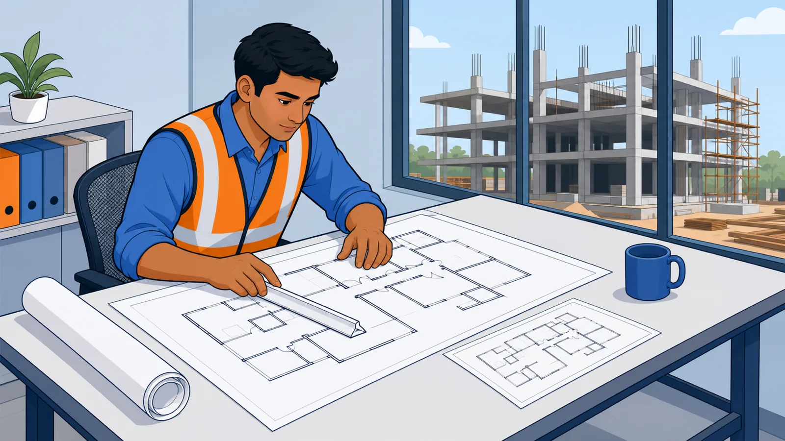
A contractor on a Pune site once ordered vitrified tile for a lower-ground lobby by laying a steel scale on a plan and multiplying. The print in his hand was an A3 copy of an A1 original. Every length he read was half the true value, every area a quarter — his tile order was short by nearly 75 percent, and the balance came at a spot-market rate with a second freight bill. Nothing on the drawing was wrong. He had misread the single most basic piece of information on the sheet: the scale.
What a scale actually says
A scale is a ratio between distance on paper and distance on the building. 1:100 means 1 unit on paper represents 100 of the same unit on site. Because Indian construction drawings dimension in millimetres (the general notes of a GFC set almost always say "all dimensions are in mm unless noted otherwise"), the useful conversions are:
| Scale | 1 mm on paper equals | 1 cm on paper equals | Typical use |
|---|---|---|---|
| 1:500 | 500 mm | 5 m | site / layout plans |
| 1:200 | 200 mm | 2 m | site plans, large floor plates |
| 1:100 | 100 mm | 1 m | floor plans, elevations, sections |
| 1:50 | 50 mm | 0.5 m | part plans, toilet and kitchen layouts |
| 1:20 | 20 mm | 200 mm | room details, wall sections |
| 1:10 / 1:5 | 10 mm / 5 mm | 100 mm / 50 mm | joinery, junction details |
These ratios are not arbitrary. IS 962, the Indian code of practice for architectural and building drawings, points to the standard scale series (1:1, 1:2, 1:5, 1:10, 1:20, 1:50, 1:100, 1:200, 1:500 and so on) — offices pick from this ladder so that everyone's scale rule works on everyone's drawings. A three-sided metric scale rule (the ₹150–300 kind sold outside every ITI and polytechnic) carries exactly these ratios.
The practical skill is converting both ways without hesitation:
- Paper to site: measured length × scale factor. 47.4 mm measured on a 1:100 plan = 47.4 × 100 = 4740 mm on site.
- Site to paper: actual length ÷ scale factor. A 3600 mm room at 1:50 = 3600 ÷ 50 = 72 mm on paper.
Why one project carries many scales
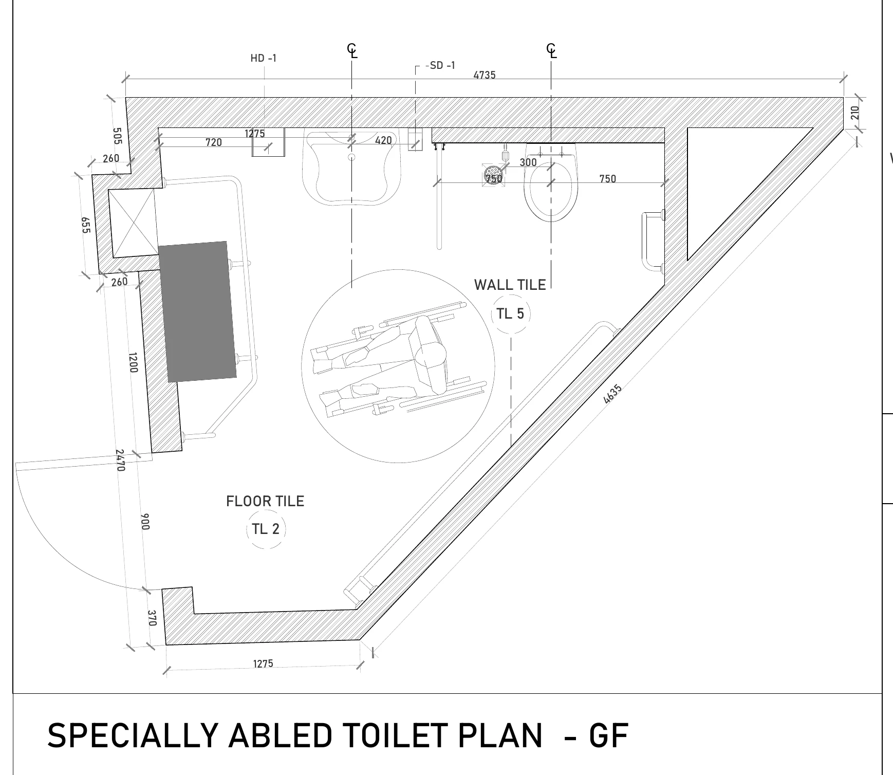
A drawing set is not drawn at one scale. The same building appears at 1:200 on the site plan, 1:100 or 1:150 on floor plans, and 1:20 or 1:10 where the detail matters. The excerpt below shows why. It is an enlarged detail from Project A, a nine-storey commercial tower — the ground-floor accessible toilet, drawn as its own plan (the course's excerpt index records it at 1:20, versus roughly 1:150 for the tower's full floor plans).
How to read this
- Read the view title at the bottom: SPECIALLY ABLED TOILET PLAN - GF. This is one room enlarged from the ground-floor plan, drawn at a detail scale.
- Trace the room envelope: 4735 dimensioned across the top, 4635 along the long splayed wall, with the external wall thickness marked 210.
- Find the CL (centreline) marks above the washbasin and the WC. The basin is positioned by the 720 and 420 dimensions; the WC centreline is tied by 300 and 750. These fixture ties only exist because the scale allows them.
- Spot the finish tags: FLOOR TILE TL 2 and WALL TILE TL 5 in circles, plus accessory tags HD-1 and SD-1 near the top - codes the finish and accessory schedules will resolve.
- See the large circle containing a wheelchair symbol: the drawn proof of manoeuvring space, with grab bars drawn on the walls beside the WC and along the left wall.
- Note the door swing arc at the bottom-left and the hatched walls - conventions the symbols lesson later in this module decodes fully.
Look at what this drawing can afford to say because it is enlarged: the room envelope is dimensioned (4735 across the top, 4635 along the splayed wall, wall thickness 210), but so are things a 1:150 floor plan physically cannot show — fixture centrelines flagged with CL symbols, the washbasin located by 720 and 420, the WC tied down by 300 and 750, tile selections called out as FLOOR TILE TL 2 and WALL TILE TL 5, accessory tags HD-1 and SD-1, grab bars drawn to shape, and a circle containing a wheelchair symbol to prove manoeuvring space exists. (For reference, India's accessibility guidance — the Harmonised Guidelines read with NBC 2016 — asks for a clear wheelchair turning circle of about 1500 mm; the enlarged scale is what lets the architect demonstrate and you verify such clearances.) At 1:150, that same room is a smudge 30 mm wide. Scale is chosen so the necessary information fits legibly — which is why, when you need a dimension for a small room, you first look for its enlarged detail instead of squinting at the floor plan.
The print-size trap
Here is the error that burned the tile contractor. Scales are stated for the original sheet size written in the title block (A0, A1, A2...). The moment a sheet is photocopied or PDF-printed to a smaller size, every stated scale on it becomes wrong:
- A1 original at 1:100, printed on A3 paper → lengths halve → the print behaves as 1:200.
- The same A1 printed on A4 → roughly 1:283 — no scale rule even has that.
Two site habits protect you:
- Calibrate against a known dimension before scaling anything. Find a written dimension — a 900 door opening, a 4735 room width — and measure it on the print. On a true 1:100 print, 900 mm must read 9 mm. If it reads 4.5 mm, you are holding a half-size print.
- Prefer the graphic scale bar if the sheet has one. A drawn bar shrinks along with the drawing, so it stays truthful at any print size — the written ratio does not.
When not to scale: the do-not-scale rule
Now the deeper rule. Almost every Indian GFC sheet carries a general note on the lines of "do not scale the drawing; follow written dimensions only" — you saw a real one in the general-notes lesson of Module 1 (/learn/drawings/drawing-set-basics/general-notes-and-legends). This note is contractual, and it exists for good reasons:
- Plotters and printers distort paper by 1–2 percent; ammonia prints and photocopies more.
- CAD drawings contain drafting slack — a wall drawn a few millimetres off while the dimension text was typed correctly.
- The stated scale may not apply to every view on the sheet (details on the same sheet are often at a different scale, labelled under each view).
So the hierarchy is: written dimension first, calculated dimension second (adding or subtracting written chains), scaled dimension a distant last — and only as a flag for a question, never as a basis for ordering material or setting out. If a dimension you need is genuinely missing, the correct move on an Indian site is an RFI (request for information) to the architect, in writing. If you scale it, build it, and it clashes with what the architect intended, the do-not-scale note means the rework is on you.
Worked example: the honest way to use a scale
You need the clear width of a corridor. The plan is 1:100 (verified against a written 900 door that measures 9 mm).
| Step | Action | Result |
|---|---|---|
| 1 | Look for a written dimension on the corridor | not given |
| 2 | Look for a chain you can subtract: block width 12000, rooms 4200 + 4200, walls 230 + 230 + 115 + 115 | 12000 − 8890 = 3110 mm |
| 3 | Scale the corridor as a cross-check only | reads about 31 mm → about 3100 mm, consistent |
| 4 | Record it as "3110 (derived)" and confirm via RFI before casting kerbs or ordering flooring | protects your bill |
The derived value (step 2) is defensible in a measurement dispute because it is arithmetic on written dimensions. The scaled value (step 3) is not.
Common mistakes
- Scaling an A3 copy of an A1 sheet — always calibrate against a written dimension first.
- Assuming one scale for the whole sheet — details in a corner of a plan sheet are usually at their own scale, written below the view title.
- Ordering material off scaled lengths — quantities must come from written dimensions; that is also what the biller and the client's QS will accept.
- Measuring a PDF without calibrating — on-screen measure tools need the same known-dimension check as a paper print.
- Ignoring the enlarged details — chasing fixture positions on a 1:150 floor plan when a 1:20 toilet detail exists wastes time and produces wrong answers.
What this sets up
Scales tell you how big things are. The next lesson covers the system that tells you where things are: grid lines, the address system that lets a drawing say "column C4, 300 off grid F" instead of "the column near the lift".
Key takeaways
- 1:100 means 1 mm on paper equals 100 mm on site; convert paper-to-site by multiplying and site-to-paper by dividing by the scale factor.
- One project uses many scales - site plans around 1:200/1:500, floor plans 1:100/1:150, and room details at 1:50 or 1:20 where fixture-level dimensions must fit.
- A stated scale is true only at the original sheet size; an A3 print of an A1 sheet turns 1:100 into 1:200, so always calibrate against a written dimension first.
- The do-not-scale general note is contractual: written dimensions govern, derived arithmetic is acceptable, scaled lengths are only a flag for an RFI.
- Never order material or set out work from scaled measurements - only written or derived dimensions survive a measurement dispute.
Verify on site
- Check the title block for the original sheet size and stated scale before measuring anything.
- Calibrate every print: measure one written dimension (a 900 door, a room width) and confirm it matches the stated scale.
- Locate the enlarged detail (toilet, kitchen, lift lobby) before chasing small dimensions on the full floor plan.
- Derive missing dimensions by adding/subtracting written chains, and mark them as derived in your notes.
- Raise a written RFI for any dimension you cannot read or derive - do not scale and build.
- Keep a metric scale rule (1:100/1:50/1:20 faces) in the site office, but treat it as a checking tool only.
Check your understanding
5 questions. Answering them marks this lesson complete — results stay on your device.
Want the free certificate?
The whole course is free and open — no signup needed to learn. Enter your details only if you want us to track your progress on this device and issue a named certificate after the final assessment.