Grid Lines: How Every Element Gets an Address
Lesson 7 of 32 · 7 min read
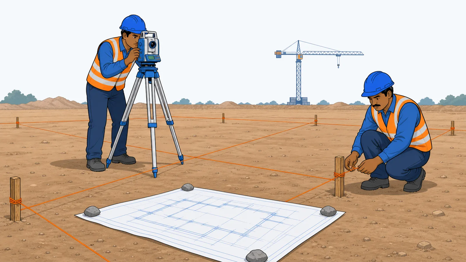
Ask a new site engineer where a column is and you will hear "the one near the office side, next to the ramp". Ask the structural consultant and you will hear "C4, on grid F, 300 off the gridline". Only one of those answers survives a phone call, a WhatsApp message, or a dispute about a shifted column. The grid is the address system of the whole project — every column, wall, beam and opening is located from it, and every setting-out check on site starts by finding it.
What a grid is
A grid is a set of imaginary reference lines drawn across the plan — usually one family of lines in each direction — with each line ending in a grid bubble: a circle, hexagon or diamond containing the grid name. Common Indian practice (consistent with IS 962-style drawing conventions) is letters along one direction and numbers along the other, so an intersection reads like B-3. Offices vary: Project A, the nine-storey commercial tower behind most of our excerpts, prefixes one family as A1...A7; Project B, the multi-tower residential project, uses hexagonal bubbles lettered F, G...; and Project A's ramp sheet uses diamond bubbles M to V. The shape and naming style change from office to office — the discipline of reading them does not.
Grid lines are drawn as long chain (dash-dot) lines. Structural members are positioned relative to them, and — critically — the same grid is shared by the architectural, structural and MEP sets. That is what lets you overlay a beam from the framing plan onto a wall from the architectural plan and know they are talking about the same place.
Reading a chained dimension string
Between grid bubbles runs the project's primary dimension string. Here is the real thing — the basement grid strip from Project A:

How to read this
- Find the circular grid bubbles along the bottom: A7, A6, A5, A4, A3, A2, A1 - note they run A7 on the LEFT to A1 on the RIGHT. Never assume direction; read the bubbles.
- Each bubble hangs from a vertical dash-dot chain line - the grid line itself.
- Read the bay chain on the upper dimension line: 11635, 7950, 8200, 7700, 8025, 12550 - each is the centre-to-centre distance between adjacent grids.
- Read the overall on the line below: 56060.
- Run the closing check: 11635 + 7950 + 8200 + 7700 + 8025 + 12550 = 56060. The chain closes exactly, so it is safe to set out from.
- Practise intermediate arithmetic: A7 to A4 = 11635 + 7950 + 8200 = 27785 - computed, never scaled.
Three things to practise on this excerpt:
- Bay-by-bay reading. Between consecutive grids the chain reads 11635, 7950, 8200, 7700, 8025, 12550 — each figure is the centre-to-centre distance between two adjacent grid lines.
- The closing check. Below the chain sits the overall: 56060. Add the bays: 11635 + 7950 = 19585; + 8200 = 27785; + 7700 = 35485; + 8025 = 43510; + 12550 = 56060. It closes exactly. Run this check on every dimension string you set out from — a chain that does not close means a typo somewhere, and you must get it resolved before driving a single peg.
- Never assume numbering direction. On this sheet the bubbles run A7 on the left to A1 on the right. Engineers who assume "numbers increase left to right" set out mirrored buildings. Read the bubbles.
A chained string is also how you compute intermediate distances without touching a scale rule. Distance from grid A7 to grid A4? 11635 + 7950 + 8200 = 27785 mm. That arithmetic — not a scaled measurement — is what you give the survey team.
Grid plus offset: locating a member exactly
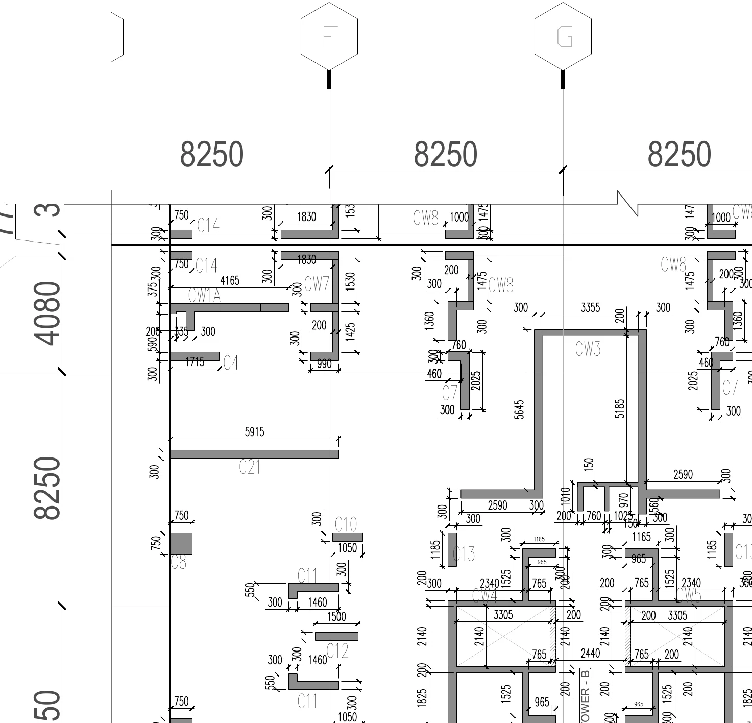
Grids locate lines; members need one more piece of information — the offset from the gridline to the member's face or centreline. This is what a setting-out plan provides. Here is a quadrant of one from Project B:
How to read this
- Find the hexagonal grid bubbles F and G at the top, with 8250 bay dimensions repeated along the top chain; the left edge carries vertical bays of 4080 and 8250.
- The grey filled shapes are structural members: compact rectangles are columns (C14, C4, C8, C21), long strips are RCC core walls (CW1A, CW3, CW7, CW8).
- Pick C14 at the top-left: small tie dimensions (750, 300) run from the gridline to the member - this grid-plus-offset pair is its complete address.
- Follow wall CW1A: a 4165 running dimension gives its length, with 300-thick segments dimensioned along it.
- Notice member thicknesses 200 and 300 repeating across the plan, and rectangles with crossed diagonals marking the lift/stair shaft zone.
- To build any of these you still need the schedule: this plan gives position, the column schedule gives size and steel.
The grey filled shapes are columns and RCC core walls, each carrying a mark (C14, C4, C21, CW1A, CW3, CW7, CW8...). Around them, small dimensions tie each member to the grid: 750 and 300 ties at C14, a 4165 running length along wall CW1A, 1715 at C4, member thicknesses of 200 and 300 repeated throughout. The lift and stair shafts show as rectangles with crossed diagonals. To place any member you need exactly two facts: which gridlines it belongs to, and the offset dimensions from those gridlines. The column schedule (Module 3, /learn/drawings/structural-drawings/column-layout-and-schedule) then tells you its size and reinforcement.
One trap deserves bold text: check whether an offset runs to the member's face or its centreline. Setting-out plans commonly dimension to faces (shuttering positions); some architectural plans dimension to centrelines. A 300-thick wall set out face-for-centre lands 150 mm wrong — enough to lose a door clearance or an elevator running dimension.
Setting out on site: the discipline
The drawing gives addresses; the site must reproduce them. Standard practice on Indian sites, from a self-builder's plot to a tower:
- Establish a baseline — usually one main gridline fixed from the plot boundary or a coordinate given by the surveyor, with two permanent stations (nails set in small concrete blocks, paint-marked) kept clear of excavation.
- Set perpendiculars by total station or, on small sites, the 3-4-5 triangle method with steel tape.
- Mark every grid from the baseline datum, not bay by bay. If you step the tape 8250, then another 8250, then another, each step's small error accumulates. Measure 8250, 16500, 24750 cumulatively from one datum instead — the drawing's overall figure (56060 on the Project A strip) is your final check.
- Transfer offsets last: from the marked gridline, offset 300 (or whatever the tie says) to the shutter face, and cross-check the member's other face against its dimensioned thickness.
- Check diagonals of every rectangular bay before concreting anything — equal diagonals prove squareness.
Worked example: pricing a grid mistake
A 230 × 600 column on a residential tower gets set out 100 mm off its gridline offset and is noticed after the first-floor slab is cast. Typical consequences, at indicative mid-2026 rates (always use your city's current quotations):
| Item | Quantity | Indicative cost |
|---|---|---|
| Structural consultant's site visit + remedial sketch | 1 visit | ₹8,000–15,000 |
| Chipping, dowelling and jacketing one column, one floor | approx 0.5 cum concrete + steel + labour | ₹35,000–60,000 |
| Delay to slab cycle while the remedy is approved | 4–7 days | shuttering and crew idle charges |
Against that, the prevention cost is a 10-minute closing check and a diagonal tape check. This is also your dispute protection: when a thekedar's team sets out from your marked grid pegs and a member still lands wrong, your dated setting-out register — grid marks checked, diagonals recorded, offsets listed — decides who pays for the jacketing. Without it, the argument defaults against whoever holds the weaker paper.
Common mistakes
- Assuming grid numbering direction instead of reading the bubbles (A7 to A1 runs right-to-left on our excerpt).
- Skipping the closing check — a chain that sums 55960 against an overall of 56060 hides a 100 mm error that will surface in the last bay.
- Stepping the tape bay by bay instead of cumulative measurement from one datum.
- Confusing face offsets with centreline offsets — read where the dimension arrowheads actually land.
- Using the architectural plan for structural setting out when the structural setting-out sheet is the one that carries member offsets; the grids should match, but members are dimensioned on the structural set.
What this sets up
You can now say where anything is. The next lesson adds the vertical dimension — levels — and untangles the pair of numbers that confuses more site engineers than any other: FFL and SSL.
Key takeaways
- A grid gives every element a unique address (like C-2); the same grid is shared by architectural, structural and MEP sheets.
- Chained dimensions read centre-to-centre between grids, and the bays must sum exactly to the overall - always run the closing check before setting out.
- Grid bubble naming and direction vary by office (A7 to A1 can run right-to-left) - read the bubbles, never assume.
- A member is located by grid plus offset; always check whether the offset runs to the face or the centreline.
- Set out cumulatively from one datum, not bay by bay, so tape errors cannot accumulate; prove squareness with diagonal checks.
- A dated setting-out register with grid checks and diagonals is what decides who pays when a member lands wrong.
Verify on site
- Verify every dimension chain closes to its overall before giving it to the survey team.
- Confirm grid numbering direction from the bubbles on the sheet, not from habit.
- Establish two protected baseline stations clear of excavation before any grid marking.
- Measure grids cumulatively from one datum; record the final overall against the drawing figure.
- For each member, note whether ties run to face or centreline before fixing shutter lines.
- Check diagonals of every bay set out and log them in the setting-out register with date and signatures.
Check your understanding
5 questions. Answering them marks this lesson complete — results stay on your device.
Want the free certificate?
The whole course is free and open — no signup needed to learn. Enter your details only if you want us to track your progress on this device and issue a named certificate after the final assessment.