Rebar Callouts Decoded: T16@200 C/C and Friends
Lesson 17 of 32 · 8 min read
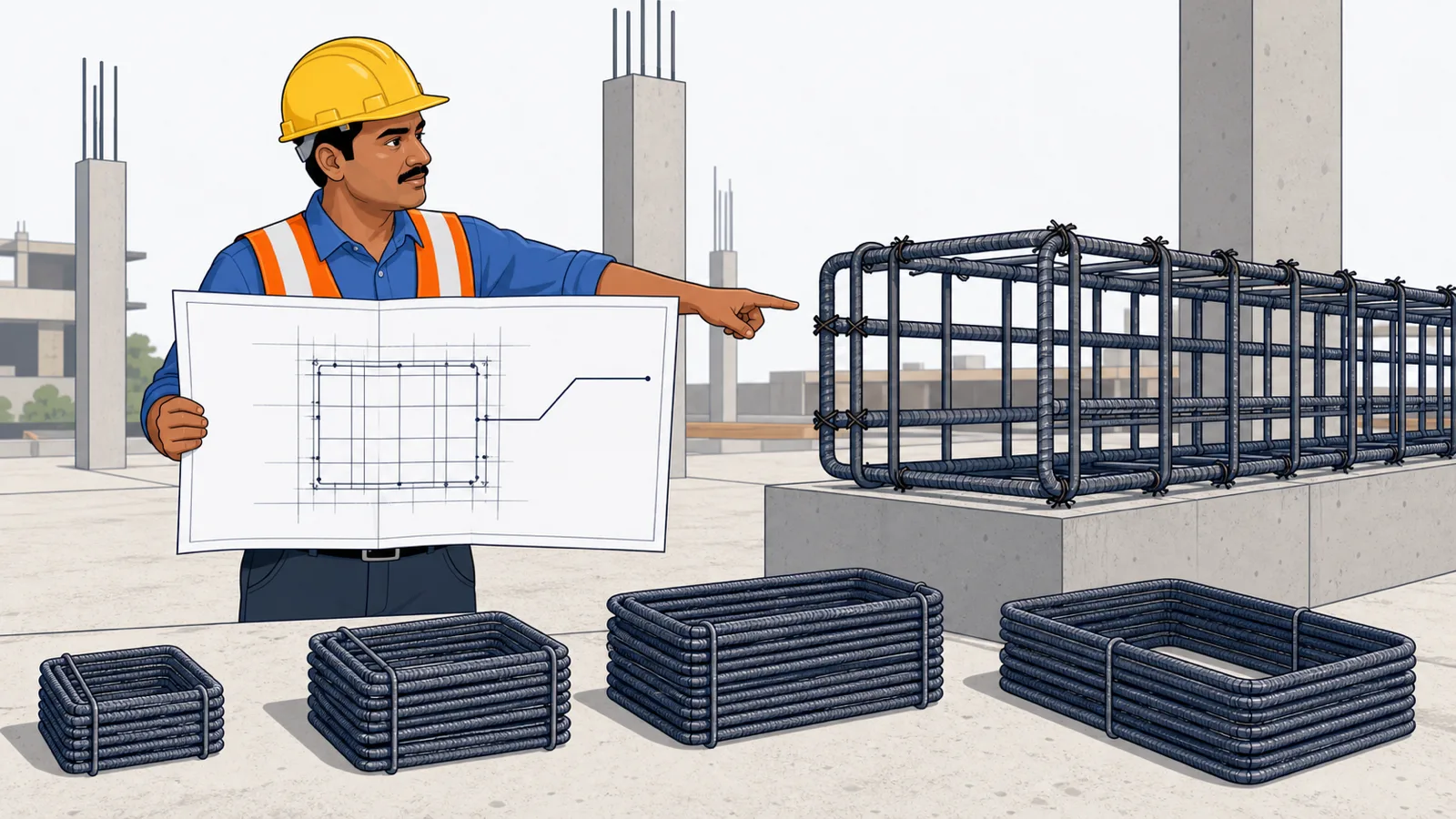
Hand a beam elevation to a bar bender and everything he cuts, bends and ties comes from strings like 3-T25(TH) and 2L-T8-150C/C. There is no paragraph of English anywhere on the sheet explaining them. At indicative mid-2026 steel rates of Rs. 52–64 per kg (check your city's current quotations), a nine-storey tower carries crores of rupees of reinforcement specified entirely in this shorthand — and one misread qualifier on a raft drawing can put you two tonnes short, or two tonnes over, on a single core wall. This lesson teaches the complete grammar from real sheets of Project A (a nine-storey commercial tower) and Project B (a multi-tower residential project), in both dialects you will meet on Indian sites.
The grammar of a rebar callout
Indian structural sheets write bars in two basic patterns:
- Counted bars (beams, columns, trimmers): count-T-diameter(qualifier), e.g. 3-T25(TH) = three bars, T-series (high-yield deformed), 25 mm dia, running THrough.
- Distributed bars (slabs, rafts, walls): T-diameter@spacing C/C, e.g. T16@200C/C = 16 mm deformed bars at 200 mm centre-to-centre, as many as the zone needs.
The T tells you the bar is high-yield deformed steel — but it does not tell you the grade. Fe 500, Fe 500D or Fe 550 comes from the structural general notes (IS 1786 defines the grades), and the notes govern. The common qualifiers:
| Qualifier | Meaning |
|---|---|
| (TH) | Through bar — runs the full length of the member |
| (EX) | Extra bar — added only in a zone, with its extent dimensioned |
| C/C | Centre-to-centre spacing (never clear gap) |
| 2L / 4L / 6L | Number of stirrup legs crossing the section |
| (1st LYR.) / (2nd LYR.) | First or second layer of a multi-layer mat |
| (ALTR.) | Alternate bars only — every second position |
Reading one beam elevation
Here is a single beam from a Project A framing sheet — the anatomy lesson for every beam you will ever read.
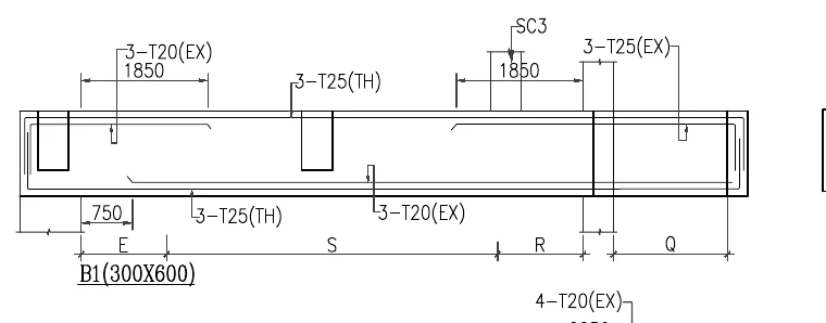
How to read this
- Find the underlined tag B1(300X600) at the bottom left — beam mark B1, 300 mm wide, 600 mm deep.
- Read the top face: 3-T25(TH) are three 25 mm through bars running the full beam; the 3-T20(EX) groups near the supports are extras, and the 1850 dimensions are their drawn extents — part of the callout, not a bar length.
- Read the bottom face the same way: 3-T25(TH) through, 3-T20(EX) added within the span. At the right support the top extras become 3-T25(EX).
- The letters E, S, R, Q between tick marks along the bottom are stirrup zones — the stirrup schedule on the same sheet decodes each letter; the 750 fixes the first zone boundary.
- The SC3 flag is a tag decoded elsewhere on the set — look it up, never guess — and the partial 4-T20(EX) at bottom right belongs to the next beam: a callout binds to the member its leader touches.
Decode it top to bottom. The tag B1(300X600) names the member and its section: 300 wide, 600 deep. The top face carries 3-T25(TH) through bars plus 3-T20(EX) extras near the support, with an extent dimension of 1850 — the extras exist only where the bending moment demands them, and the 1850 is part of the callout, not decoration. The bottom face mirrors the logic: 3-T25(TH) through, 3-T20(EX) added in the span. At the right support the top extras step up to 3-T25(EX).
Why extras? Steel area follows the bending moment. At the left support the top steel is 3-T25 + 3-T20:
| Location | Bars | Area |
|---|---|---|
| Top, midspan | 3-T25(TH) | 3 x 491 = 1,473 mm² |
| Top, left support | 3-T25(TH) + 3-T20(EX) | 1,473 + 3 x 314 = 2,415 mm² |
The support carries 64 percent more top steel than midspan — delivered not by thickening the through bars but by short extras. If you take off only the (TH) bars, your BBS is light by exactly those extras; if you run the (EX) bars full length "to be safe", you gift the scrap dealer three bars x several metres of T20 per beam.
One more habit this excerpt builds: the flag SC3 above the beam is a tag pointing elsewhere on the set. When you meet a tag you cannot decode, the sheet legend or general notes decode it — never guess. And note the stray 4-T20(EX) at the bottom right: it belongs to the next beam. A callout binds to the member its leader line touches, not to whatever sits nearest.
Zone letters and the stirrup schedule
Under beam B1 run the letters E, S, R, Q between tick marks. They are not dimensions — they are stirrup zones, decoded in a schedule elsewhere on the same sheet:
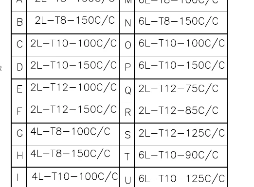
How to read this
- Each row pairs a zone letter with a stirrup spec written legs-T-dia-spacing.
- Read row E: 2L-T12-100C/C — two-legged stirrups of 12 mm deformed bar at 100 mm centres.
- The leading number plus L is the leg count: rows G, H, I switch to 4L and rows N through U to 6L — multi-legged stirrups for wider members.
- Compare rows Q (75), R (85), S (125): the same 2L-T12 stirrup at three spacings — zones exist so spacing can tighten where shear demands it.
- Match the letters E, S, R, Q from the beam elevation excerpt to these rows to fix every stirrup in beam B1.
Each row is legs-T-diameter-spacing. Row E = 2L-T12-100C/C: two-legged stirrups of T12 at 100 centres. Rows G–I and N–U show 4L and 6L — four- and six-legged stirrups for wide members where two legs cannot restrain every bar. Now map B1's zones through the table:
| Zone on B1 | Schedule row | Meaning |
|---|---|---|
| E | 2L-T12-100C/C | 2-leg T12 at 100 |
| S | 2L-T12-125C/C | 2-leg T12 at 125 |
| R | 2L-T12-85C/C | 2-leg T12 at 85 |
| Q | 2L-T12-75C/C | 2-leg T12 at 75 |
Spacing tightens toward the supports — shear is highest there, and seismic detailing (IS 13920) densifies hoops near beam ends. The 750 dimension at the left fixes the first zone boundary. Miss the zone letters and price every stirrup at the midspan spacing, and your stirrup count is short by a third on this beam.
Layered and alternate callouts on rafts
Raft and mat foundations stack bars in layers, and the callout says which layer each band belongs to. From Project B's raft sheet:
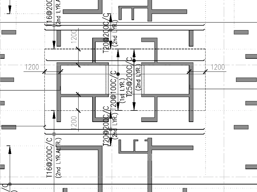
How to read this
- The grey shapes are core walls standing on the raft; the dashed rectangle bounds the extra-reinforcement zone beneath them.
- Centre callouts stack two layers in one plan zone: T20@100C/C (1st LYR.) with T25@200C/C (2nd LYR.) above it.
- Either side, the second layer relaxes to T20@200C/C (2nd LYR.) — same layer, wider spacing, lighter zone.
- At the left edge, T16@200C/C (2nd LYR.ALTR.) places alternate bars only — every second position, sitting between the parent bars.
- The 1200 dimensions with arrows fix how far each band extends past the wall faces. Extents are part of the callout: no extent, no take-off.
Four callouts share one zone under the core walls: T20@100C/C (1st LYR.) with T25@200C/C (2nd LYR.) stacked over it in the heavy central band; T20@200C/C (2nd LYR.) either side where demand relaxes; and T16@200C/C (2nd LYR.ALTR.) further out — alternate bars of the second layer only, sitting between the parent bars. The 1200 dimensions fix how far each band runs past the wall faces.
The money in this drawing is in the qualifiers. A quick worked count for the central extra band, assuming the band's bars are 6.4 m long:
| Step | Calculation | Value |
|---|---|---|
| Bars across 1,200 wide band at 100 C/C | 1200/100 + 1 | 13 bars |
| Length of steel | 13 x 6.4 m | 83.2 m |
| Weight (T20 at 2.469 kg/m) | 83.2 x 2.469 | 205 kg |
| Cost at Rs. 58/kg (indicative mid-2026) | Rs. 11,900 |
That is one band, of one layer, under one core wall — invisible to anyone who reads only the biggest text on the sheet. Multiply by every band on a 1,200-thick raft and misreading LYR/ALTR moves your steel order by tonnes.
The second dialect: 12 dia @ 6 inch C/C
Consultant-detailed sheets like the ones above speak pure millimetres. But a large share of Indian residential and compound-wall drawings — especially architect-led or older sets — write the same idea as 12Ø @ 6" C/C: 12 mm diameter (the Ø symbol is just "dia") at 6 inch centres, on a sheet whose other dimensions are in millimetres. You will read this dialect on Project A's boundary-wall details in the next lesson.
Three rules keep you safe:
- Ø carries no grade information at all. T at least promises deformed high-yield bars; Ø could be anything — the general notes must say Fe 500 (or the rare leftover Fe 415 spec). Confirm before ordering.
- Convert to millimetres before any BBS arithmetic. 6" = 152.4 mm; site practice rounds to 150 mm (4" to 100, 8" to 200, 9" to 225). The rounding is conservative — slightly more bars — and it is the near-universal convention, but write the convention you used on the BBS itself so the bill checker follows your maths.
- Never mix units inside one calculation. The classic error is dividing a millimetre wall length by "6" as if it were 6 mm or 60 mm. A 10 m wall at 6" C/C needs 10000/150 + 1 = 67.7, say 68 bars — not 1,668 of anything.
As a comparison of steel intensity across dialects: T16@200C/C lays 5 bars per metre at 1.580 kg/m = 7.9 kg/m² per layer per direction; 12Ø@6"C/C lays 6.67 bars per metre at 0.889 kg/m = about 5.9 kg/m². Two strings that look nothing alike, one calculation once you convert.
Common mistakes
- Reading an extent dimension as a bar length. The 1850 on B1 is how far the extras run from their reference point — the cutting length needs both sides plus the support width (next lesson).
- Treating (EX) bars as running full length, or omitting them entirely because the (TH) callout "already covers the top".
- Assuming T means Fe 415. On current sets it almost always resolves to Fe 500/Fe 500D via the general notes — the lap and development lengths change with grade, so this is not cosmetic.
- Ignoring LYR/ALTR qualifiers on rafts — the difference between 100 and 200 effective spacing is a factor of two in steel.
- Unit-mixing in the inch dialect — convert everything to mm first, and record the conversion.
What comes next
You can now read what steel a drawing wants and where. The next lesson turns callouts into the number the bar bender actually needs — the cutting length — using the bending, curtailment and lap rules printed on the same sheets. For the arithmetic that underpins it (d²/162, hook and bend allowances derived from IS 2502), see the QS course lesson Steel and BBS Basics.
Key takeaways
- Counted bars read count-T-dia(qualifier); distributed bars read T-dia@spacing C/C — and every qualifier (TH, EX, LYR, ALTR, nL) changes the quantity.
- T means high-yield deformed bar but never states the grade — Fe 500/Fe 500D comes from the structural general notes.
- Extra (EX) bars exist only within their dimensioned extents; reading an extent as a bar length or running extras full length are both costly errors.
- Stirrup zone letters under a beam resolve through the stirrup schedule to legs-dia-spacing, tightening toward supports.
- The diameter-inch dialect (12 dia @ 6 inch C/C) must be converted to mm — 6 inch is taken as 150 mm by near-universal site convention — before any BBS arithmetic.
- On rafts, LYR and ALTR qualifiers are worth tonnes: alternate second-layer bands halve the effective spacing where they apply.
Verify on site
- Pull the structural general notes and confirm the steel grade (Fe 500/Fe 500D) before pricing any callout.
- Highlight every (EX) callout on the sheet and trace its extent dimension with a scale before take-off.
- List the stirrup zone letters of each beam and write the decoded legs-dia-spacing next to each on your print.
- On raft sheets, mark 1st layer, 2nd layer and ALTR bands in three different highlighter colours before counting.
- If the sheet uses inch spacing, write the mm conversion you adopted on the BBS header so the bill checker follows it.
- Query any tag you cannot decode (like a schedule flag) through the legend or an RFI — never assume.
Check your understanding
5 questions. Answering them marks this lesson complete — results stay on your device.
Want the free certificate?
The whole course is free and open — no signup needed to learn. Enter your details only if you want us to track your progress on this device and issue a named certificate after the final assessment.