Cutting Lengths from Sections and Details
Lesson 18 of 32 · 7 min read
When the steel bill is argued at month end, nobody disputes that beam B1 exists. The argument is always the cutting length — how long each bar mark really is, whether the laps were required or convenient, whether the extras stopped where the drawing stops them. Every number you need is already printed on the structural set, mostly on one unglamorous sheet: the typical details. This lesson reads that sheet from Project A (the nine-storey commercial tower) and converts its rules into millimetres, then does the same on a boundary-wall section written in the diameter-inch dialect.
The recipe, and where its numbers come from
Every cutting length is one equation:
Cutting length = sum of outer dimensions + hook allowances − bend deductions
The allowances are settled convention, derived in the QS course lesson Steel and BBS Basics: U-hooks add 9d per hook (IS 2502 geometry, minimum 75 mm); seismic stirrup hooks are 135° with a 10d extension, minimum 75 mm (that is the IS 13920 definition of a hoop); bend deductions run 1d for 45°, 2d for 90°, 3d for 135° by standard BBS convention. What this lesson adds is the drawing-reading half: where the outer dimensions themselves come from.
The typical-details sheet: rules that price every beam
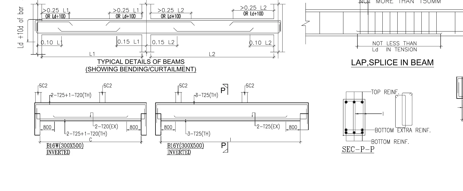
How to read this
- Read the title first: TYPICAL DETAILS OF BEAMS (SHOWING BENDING/CURTAILMENT) — this sheet states rules, not one specific beam.
- Along the top, the repeated extents read greater than 0.25 L1 OR Ld+10D — how far top support bars must run into each span, whichever is more.
- Along the bottom, 0.10 L1 and 0.15 L1 / 0.15 L2 mark where bottom bars may be curtailed, measured from the supports as fractions of each clear span.
- The left margin note Ld +10d of bar is the end-support anchorage; on the right, LAP,SPLICE IN BEAM requires laps NOT LESS THAN Ld IN TENSION, with the cropped note above capping stirrup spacing over the lap at 150 mm.
- Below, beams B16W(300X500) and B16Y(300X500), both INVERTED, apply the rules: mixed group 2-T25+1-T20(TH), extras 2-T20(EX) and 2-T25(EX) with 800 extents, and the section flag P.
- SEC-P-P at the bottom right names each group — TOP REINF., BOTTOM EXTRA REINF., BOTTOM REINF. — the legend that connects elevation callouts to positions in the section.
This is not a drawing of any one beam — the title says so: TYPICAL DETAILS OF BEAMS (SHOWING BENDING/CURTAILMENT). It is the rulebook the detailer applied to every beam on the job, and the rulebook you apply whenever a specific elevation leaves something undimensioned. Decode it:
- Top steel extents: the repeated note greater than 0.25 L1 OR Ld+10D fixes how far top support bars run into each span — a quarter of the clear span, or the development length plus 10 diameters, whichever is more.
- Bottom curtailment: the marks at 0.10 L1 (end supports) and 0.15 L1 / 0.15 L2 (interior supports) are where bottom bars may stop. Curtailment positions are measured from the support, in fractions of the clear span — so the same rule yields different millimetres in every bay.
- End anchorage: the margin note Ld +10d of bar is the hook-down length into the end support.
- Laps: the LAP,SPLICE IN BEAM detail demands laps NOT LESS THAN Ld IN TENSION, and the partially cropped note above it caps stirrup spacing over the lap at 150 mm — laps are confined zones, not just overlaps.
- Below the rules sit two real beams — B16W(300X500) and B16Y(300X500), both marked INVERTED — applying them, with 800 extents on their (EX) bars and the section flag P leading to SEC-P-P, which names each bar group: TOP REINF., BOTTOM EXTRA REINF., BOTTOM REINF. Note the group 2-T25+1-T20(TH): callouts can mix diameters in one group (area = 2 x 491 + 314 = 1,296 mm²) — take off each diameter separately.
What is Ld? IS 456 gives development length as a formula (clause 26.2.1: bar dia times stress over four times bond stress). Worked through for deformed Fe 500 bars in tension it comes to roughly 57d in M20, 49d in M25, 45d in M30 concrete. Project A's slab sheets specify M-30, so for a T20 top bar, Ld is about 45 x 20 = 900 mm, and Ld+10D = 1,100 mm.
Worked example 1: an extra top bar, end to end
Take the 3-T20(EX) top extras over an interior support, with the drawn extent 1850 on each side of the support (as on beam B1 in the previous lesson). Assume a 400 mm wide support — state the assumption on your BBS and correct it from the column schedule.
| Step | Calculation | Value |
|---|---|---|
| Extent, left of support | read from drawing | 1,850 mm |
| Support width | column schedule (assumed here) | 400 mm |
| Extent, right of support | read from drawing | 1,850 mm |
| Bends/hooks | straight bar, none shown | 0 |
| Cutting length | 1850 + 400 + 1850 | 4,100 mm |
| Weight, 3 bars | 3 x 4.10 x 2.469 | 30.4 kg |
Sanity-check the detailer against the typical sheet: if the clear span is 7.0 m, the rule demands at least 0.25 x 7000 = 1,750 mm or Ld+10D = 1,100 mm — the drawn 1,850 satisfies both. When a drawn extent comes out less than the typical rule, that is an RFI, not a judgement call.
The classic mistake here is billing the extras at 1,850 (one extent, forgetting the far side and the support) or at the full beam length (treating EX as TH). At Rs. 58/kg, three T20 extras taken full-length over a 7 m beam instead of 4.1 m adds about 21 kg — Rs. 1,250 of phantom steel on one bar mark of one beam.
Worked example 2: the 600 lap that is exactly 50d
Now the second dialect, on Project A's boundary-wall stem:
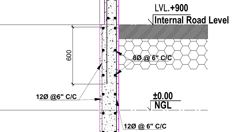
How to read this
- Fix the datums first: ±0.00 NGL is natural ground and LVL.+900 Internal Road Level sits 900 mm above it; earth fill is the hexagonal hatch against the stem.
- The 12Ø @6" C/C callouts point to the vertical bars in the stem — 12 mm dia at 6 inch (about 150 mm) centres.
- The 8Ø @ 6" C/C callout points to the dotted bar sections in both faces — the horizontal distribution bars crossing the section.
- The 600 vertical dimension marks the zone where one set of vertical bars terminates against the continuing face bars — a curtailment lap: 600/12 = 50d.
- Note the unit mix on one detail: levels and the 600 in millimetres, bar spacing in inches — convert everything to mm before it enters the BBS.
The section shows the retaining stem between two datums — ±0.00 NGL (natural ground) and LVL.+900 Internal Road Level — with earth fill hatched against one face. The verticals are 12Ø @6" C/C (12 mm at ~150 mm centres); the dotted bar sections in both faces are the 8Ø @ 6" C/C horizontal distribution bars. And there is a vertical dimension of 600 marking the zone where one set of vertical bars terminates while the face bars continue — a curtailment lap.
Check that 600 like a QS, not a draughtsman:
| Check | Calculation | Verdict |
|---|---|---|
| Lap in bar diameters | 600 / 12 | 50d — the classic site convention |
| Code demand if concrete is M25 (Fe 500, tension) | ~49d = 588 mm | 600 OK |
| Code demand if concrete is M20 (Fe 500, tension) | ~57d = 684 mm | 600 is short — RFI |
The same drawn number is compliant or deficient depending on a concrete grade written somewhere else entirely — the general notes. That cross-check habit (callout x grade x lap table) is what separates reading a drawing from looking at it. Compound walls are commonly M20–M25 and regional practice varies; confirm the grade before you defend or dispute the 600.
Mixed units are the other trap on this sheet: the 600 and the levels are millimetres while bar spacing is in inches. Convert everything to mm on the BBS, and note the conversion.
Where laps go — and who pays for them
IS 456 (clause 26.2.5.1) sets the floor: laps in flexural tension are Ld or 30d, whichever is greater; direct tension 2Ld or 30d; compression laps not less than 24d. Laps must be staggered, and the typical detail adds its own conditions — confined by stirrups at max 150 mm here. Position matters as much as length: the typical sheets place bottom-bar laps near supports and top-bar laps near midspan, away from each bar's maximum-moment zone; your sheet's own detail governs.
The rupee angle: TMT arrives in 12 m stock, so laps beyond the drawing's requirement are the bar bender's convenience, and each 16 mm lap at 50d consumes 0.8 m = 1.26 kg = about Rs. 73. The defence against convenience-lap billing is an issued cutting plan — built in the QS course lesson BBS for a Slab and a Beam — plus a work-order line that only drawing-required laps are payable. That single line, agreed before mobilisation, has ended more month-end arguments than any measurement ever will.
Common mistakes
- Measuring curtailment fractions from the wrong origin. 0.15 L2 is measured from the support face along the clear span L2 — not from the column centreline, not from the previous span.
- Using one Ld for every bar. Ld scales with diameter and changes with concrete grade; a T25 in M30 needs ~1,125 mm while a T12 needs ~540 mm.
- Ignoring the support width between two drawn extents (the 4,100 vs 3,700 error in Example 1).
- Accepting a drawn lap without checking d and grade — 600 is generous for 10 mm bars, exactly 50d for 12 mm, and deficient for 16 mm anywhere.
- Forgetting bend deductions on hooked ends — every 90° bend over-counts 2d if you simply add leg lengths.
What comes next
Beams taught you rules-plus-extents. Slabs and rafts move the same information into tables — a Schedule of Slab row can hide a floor's worth of steel in six cells. The next lesson reads those tables straight into a bar list.
Key takeaways
- Cutting length = outer dimensions + hook allowances (9d U-hook, 10d stirrup hook, min 75 mm) − bend deductions (1d/2d/3d for 45°/90°/135°).
- Typical-details sheets fix top-bar extensions (0.25L or Ld+10d) and bottom curtailment points (0.10L end, 0.15L interior) for every beam on the job.
- Curtailment fractions are of the clear span, measured from the support face — the same rule gives different millimetres in every bay.
- Ld for deformed Fe 500 in tension is roughly 57d (M20), 49d (M25), 45d (M30) — a drawn lap of 600 is exactly 50d for a 12 mm bar, and adequate or deficient depending on grade.
- A bar over a support is extent + support width + extent — forgetting the support width or the far extent are the two classic under-measures.
- Only drawing-required laps are payable by common practice; an issued cutting plan is your defence against convenience laps.
Verify on site
- Locate the typical bending/curtailment sheet in your set and pin it next to the framing plans — it prices what elevations leave undimensioned.
- Write the job's Ld values (per dia, per concrete grade) on the front of your BBS file before computing any length.
- For every (EX) bar, record extent + support width + extent, with the support width taken from the column schedule.
- Check each drawn lap: divide by bar dia and compare against the grade-correct lap table; raise an RFI where short.
- Confirm stirrup spacing is densified to the drawing value (150 max here) across every lap zone before concreting.
- On mixed-unit sheets, convert inch spacings to mm in writing on your print before take-off.
Check your understanding
5 questions. Answering them marks this lesson complete — results stay on your device.
Want the free certificate?
The whole course is free and open — no signup needed to learn. Enter your details only if you want us to track your progress on this device and issue a named certificate after the final assessment.