Plans, Sections and Elevations: Three Views, One Building
Lesson 2 of 32 · 7 min read
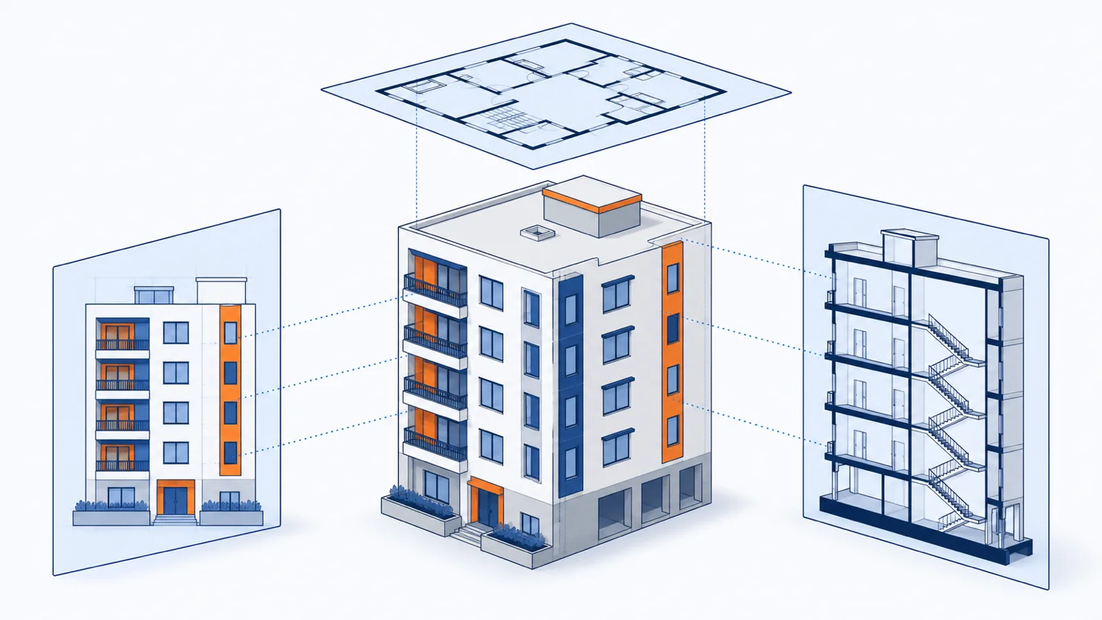
Ask a fresher what a floor plan is and you will hear "the top view". Close - but wrong in a way that costs money. A plan is not a view from above; it is a horizontal cut through the building, conventionally taken about 1.2 m above the floor, looking down. That is why doors appear as openings with swing arcs, why windows show as lines in the wall, and why anything above the cut - a loft, a beam, a high window - shows dashed or not at all. Misunderstanding what each view can and cannot show is how stairs get built with the wrong number of risers and landings get cast at the wrong level.
Three views, three cuts
- Plan: horizontal cut, looking down. Best for positions - where walls, doors, columns and fittings sit, and the dimensions between them.
- Section: vertical cut, looking sideways. Best for heights - floor-to-floor levels, headroom, depths below ground, how a stair climbs. Whatever the cutting plane slices through is drawn with a heavy outline or hatch.
- Elevation: no cut at all - the outside face of the building seen straight on. Best for facade materials, window positions, external levels.
One building, three complementary instruments. A plan physically cannot tell you a stair's headroom; a section physically cannot tell you how wide the flight is at a point it does not cut. Reading drawings means moving between views deliberately, and the device that connects them is the section marker.
The section marker: a signpost between sheets
A section marker on a plan is a circle (carrying the section's letter or number) with a filled triangle. The triangle's direction is the direction you are looking; the line or pair of markers across the plan is where the knife cuts. See a marker labelled Q, and somewhere in the set - same sheet or another - there is a drawing titled SECTION Q-Q. That suffix "-Q-Q" means "cut from marker Q to marker Q".
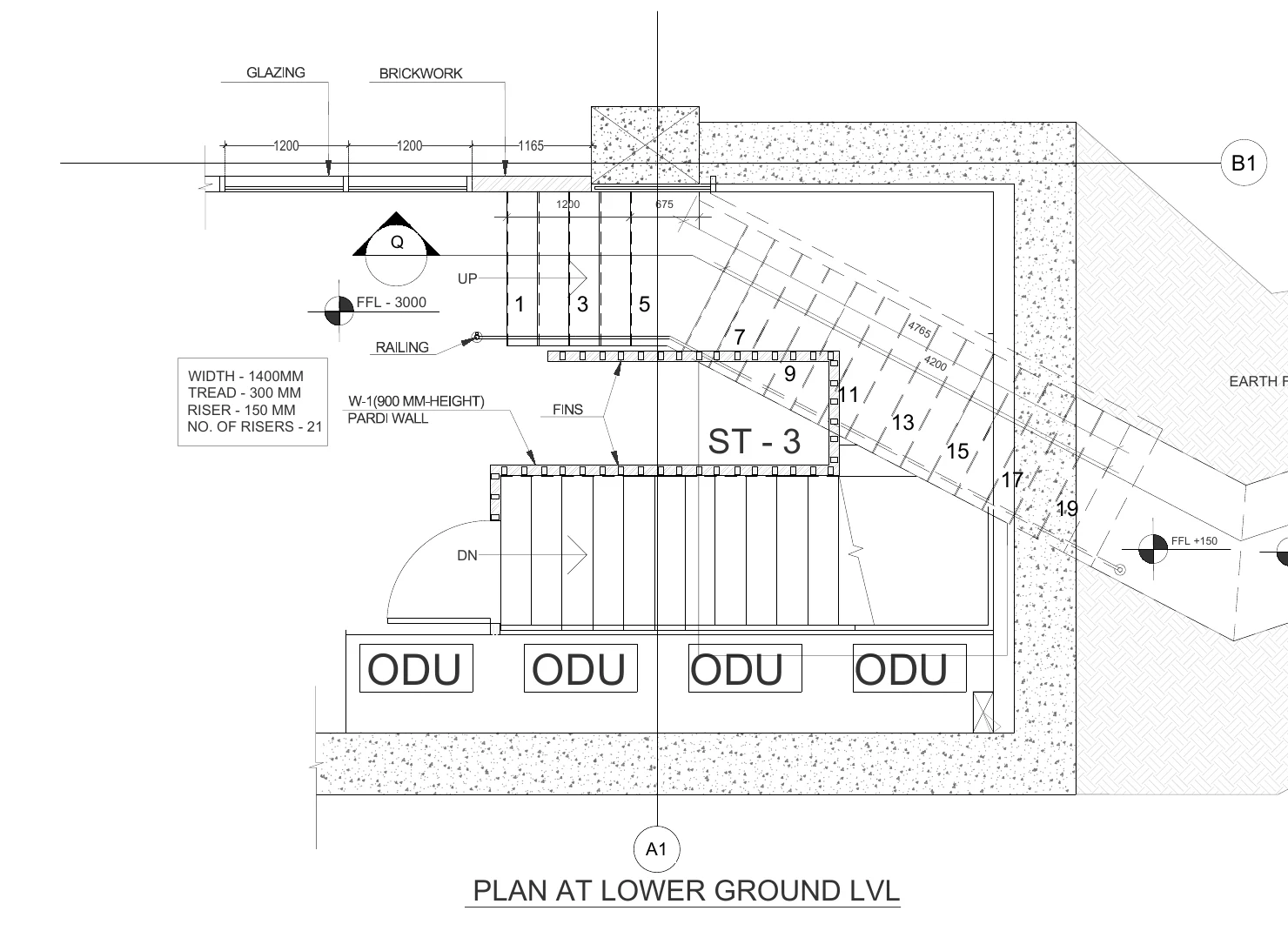
Now let us read a real one. This is the lower-ground stair plan of Project A, the nine-storey commercial tower.
How to read this
- Read the drawing title first: PLAN AT LOWER GROUND LVL, with the stair itself labelled ST - 3 and grid bubbles B1 (right edge) and A1 (bottom) locating it.
- Find the section marker: the circle marked Q with a filled black triangle at the top of the stair - it promises a drawing titled SECTION Q-Q elsewhere in the set.
- Follow the riser numbering from the UP arrow: 1, 3, 5 up the short run, then 7, 9, 11, 13, 15, 17, 19 along the long flight. A DN arrow marks the run going down from this level.
- Read the boxed spec on the left: WIDTH - 1400MM, TREAD - 300 MM, RISER - 150 MM, NO. OF RISERS - 21.
- Anchor the levels: the marker at the stair foot reads FFL - 3000; out right, where the stair lands, another reads FFL +150.
- Scan the context: GLAZING and BRICKWORK bands above with 1200 / 1200 / 1165 dimensions, a RAILING and FINS, the W-1 pardi wall noted 900 mm high, ODU boxes beside the stair and the earth-fill hatch at the right edge.
Spend a minute on this excerpt - it repays close reading:
- The title under the drawing says PLAN AT LOWER GROUND LVL, and the staircase is labelled ST - 3 (stair number 3 of the project).
- The Q section marker (circle with a filled triangle) sits at the top-left of the stair, telling you a section drawing named Q-Q exists.
- Risers are numbered along the flight - you can read 1, 3, 5 up the first run and the numbering continuing 7, 9, 11, 13, 15, 17, 19 along the long flight. UP and DN arrows tell you which way each run climbs from this level.
- The boxed specification states: WIDTH - 1400MM, TREAD - 300 MM, RISER - 150 MM, NO. OF RISERS - 21.
- Level markers anchor the stair vertically: FFL - 3000 at the foot (this is a lower-ground level, 3.0 m below the project datum) and FFL +150 out on the right where the stair lands.
- Around the stair, the plan names what it touches: GLAZING and BRICKWORK above (with 1200 / 1200 / 1165 dimensions), a RAILING, FINS, a W-1 pardi wall noted 900 mm high, an EARTH-FILL hatch on the right, and a row of ODU boxes (outdoor AC units) parked beside the stair.
Following the marker to SECTION Q-Q
How to read this
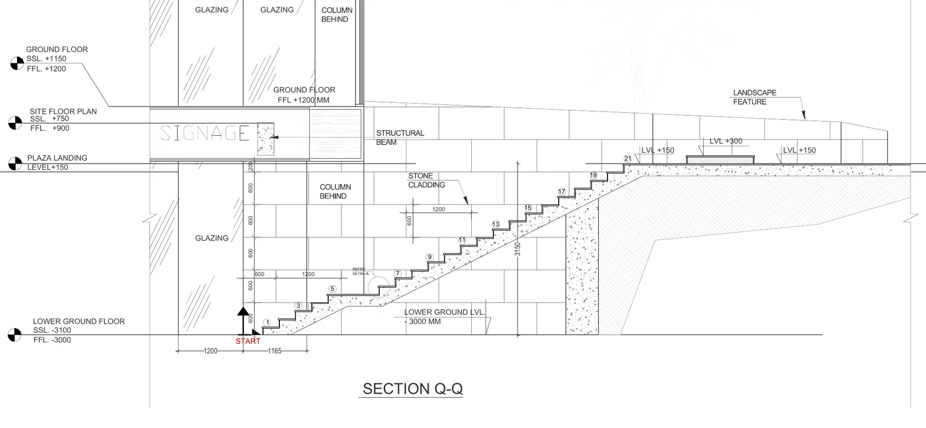
- Confirm you found the right drawing: the title reads SECTION Q-Q - the section cut at marker Q on the stair plan.
- Read the level flags on the left, bottom to top: LOWER GROUND FLOOR SSL. -3100 / FFL. -3000, PLAZA LANDING LEVEL +150, SITE FLOOR PLAN SSL. +750 / FFL. +900, GROUND FLOOR SSL. +1150 / FFL. +1200.
- Find the red START marker at the foot of the flight, then follow the circled riser numbers 1, 3, 5 ... 19, 21 up to the landing.
- Read the vertical dimension 3150 spanning the climb, and check it: 21 risers x 150 mm = 3,150 mm = from FFL -3000 up to +150. Plan, spec and section all agree.
- Notice what only a section can show: the STONE CLADDING coursing (1200 / 600), the STRUCTURAL BEAM and COLUMN BEHIND, GLAZING and SIGNAGE above, and the LANDSCAPE FEATURE at LVL +150 / +300 on the right.
This is the section that plan promised - titled SECTION Q-Q. Everything the plan could not say about height is here:
- On the left margin, level flags stack up the storeys: LOWER GROUND FLOOR SSL. -3100 / FFL. -3000, PLAZA LANDING LEVEL +150, SITE FLOOR PLAN SSL. +750 / FFL. +900, and GROUND FLOOR SSL. +1150 / FFL. +1200. (SSL is the structural slab level, FFL the finished floor level - module 2 devotes a full lesson to this pair; for now, notice both exist.)
- The risers climb as circled numbers - 1, 3, 5, 7, 9, 11, 13, 15, 17, 19, 21 - from a red START marker at the bottom of the flight up to the landing.
- A vertical dimension of 3150 spans the climb, and the note LOWER GROUND LVL - 3000 MM pins the starting level.
- The section also reveals what surrounds the stair vertically: STONE CLADDING on the wall (with 1200 and 600 coursing dimensions), a STRUCTURAL BEAM, COLUMN BEHIND, GLAZING above, SIGNAGE, and a LANDSCAPE FEATURE at the top right with levels LVL +150 and LVL +300.
Notice the plan and section agreeing with each other: the plan's FFL - 3000 at the stair foot matches the section's lower-ground FFL -3000; the plan's FFL +150 landing matches the section's PLAZA LANDING LEVEL +150; even the 1200 and 1165 dimensions near the start of the flight appear in both views. That agreement is not decoration - it is the thing you check.
The worked check: do the risers add up?
Here is the sixty-second verification a trained reader performs before a single stair shutter is fixed:
| Step | Reading | Value |
|---|---|---|
| Level at foot of stair (plan and section) | FFL lower ground | -3000 mm |
| Level at landing (plan and section) | Plaza landing | +150 mm |
| Required rise | 150 - (-3000) | 3,150 mm |
| Spec box: risers | 21 nos x 150 mm | 3,150 mm |
| Section's own vertical dimension | printed on Q-Q | 3,150 |
Three independent numbers, one answer. If the spec said 20 risers, or the landing read +300, the mismatch would surface here - on paper, where it costs nothing. For context, the 150 mm riser / 300 mm tread pairing sits within the limits NBC 2016 (Part 3) prescribes for public buildings, which cap riser height and set minimum treads by occupancy - check the table for your building type; residential limits are more relaxed.
And the money angle: a stair flight cast with the wrong riser count or landing level is one of the most expensive small mistakes on a site - the waist slab, steps and often the landing must be demolished and recast, easily Rs. 25,000 to 40,000 of concrete, steel, shuttering and labour for one flight (indicative mid-2026 range) plus the days lost while the only vertical route on that wing is a rubble pile. The sixty-second check above is what that money buys you for free. And if the drawing itself contains the mismatch, a dated written query - before you build - moves the cost of the error to where it belongs. Document first, cast second.
Common mistakes
- Building a stair from the plan alone. The plan gives width, treads and position; only the section gives you the climb, landings and headroom. Read both, always.
- Ignoring the triangle's direction. Two sections cut on the same line looking opposite ways show different walls. The filled triangle points the way you look.
- Missing UP/DN arrows. Flights get built mirrored when nobody checks which way the numbering climbs from the level you are standing on.
- Assuming an elevation is a section. An elevation shows the outside face only; nothing in it is cut, so internal levels read from it are guesses.
What comes next
You can now name the three views and chase a section marker across sheets. The next lesson zooms into the corner of the sheet you should actually read first - the title block, the sheet number, and the revision table that says whether the beautiful drawing you are holding is already obsolete.
Key takeaways
- A plan is a horizontal cut about 1.2 m above the floor, a section is a vertical cut, and an elevation is the uncut outside face - each answers questions the others cannot.
- A section marker's letter names the section, its filled triangle shows the viewing direction, and the matching drawing is titled SECTION letter-letter.
- On the Project A stair, plan and section agree: FFL -3000 at the foot, +150 at the landing, and 21 risers x 150 mm = 3,150 mm of rise.
- Verify stairs on paper: required rise from level flags must equal riser count times riser height before any shutter is fixed.
- Riser and tread limits vary by occupancy under NBC 2016 Part 3 - public buildings are stricter than residential; check the table for your case.
- A wrongly cast flight costs Rs. 25,000-40,000 (indicative) to demolish and recast - the sixty-second arithmetic check is free.
Verify on site
- Before setting out any stair, find its section drawing via the section marker - never work from the plan alone.
- Check riser count x riser height against the difference between the FFL flags at the foot and the landing.
- Confirm UP/DN arrows against the level you are standing on before marking the first riser.
- Compare the levels printed on the plan with the same levels on the section - they must match exactly.
- Verify tread and riser dimensions against the NBC limits applicable to your building's occupancy.
- Raise a dated written query for any mismatch between views before casting, and keep the reply on file.
Check your understanding
5 questions. Answering them marks this lesson complete — results stay on your device.
Want the free certificate?
The whole course is free and open — no signup needed to learn. Enter your details only if you want us to track your progress on this device and issue a named certificate after the final assessment.