
Private sample · shared on request
One drawing set in. Take-off sheet out.
A real high-rise our AI pipeline processed — 2 basements + ground + 9 floors + terrace. Identity masked, numbers real. This page follows the same format your own delivery arrives in.
- Input
- 1 architectural DWG, 12 sheets
- Sector
- Residential high-rise, retail at ground
- Extent
- B2 → terrace, 17 storeys (−11.2 m to +40.2 m)
- CAD read
- 32,670 entities · 95 layers · 129 dimensions
- Model built
- 15,490 elements, IFC4, 0 validation errors
- Status
- Sample — identity masked, numbers real
Read first: what's measured, what's estimated
Every SiteSetu bill separates M from E. Measured rows trace to the drawing; estimated rows state their assumption on the row itself. That split is the whole point — you always know which numbers to trust and which need one more drawing from your side.
Measured (M) — from the drawings themselves
- • All structural geometry: 530 columns, 1,640 beams, 1,489 slab panels, 83 walls, 71 stair flights — rebuilt from the plans and counted from the model, not typed in.
- • 12,039 m³ of concrete as solid volumes of modelled members.
- • 181 doors with sizes, from the drawing's own door schedule.
- • Floor areas cross-checked against the drawing's printed unit labels.
Estimated (E) — flagged, never hidden
- • Facade quantities ride on block counts — a facade shop set upgrades them to measured.
- • Partition wall volumes need section heights; linework lengths are the starting point.
- • Rebar is not measurable from an architectural set — it needs the BBS, and the sheet says so instead of inventing a number.
- • 2,700+ ambiguous items were routed to the human review queue on this project.
You send the drawings
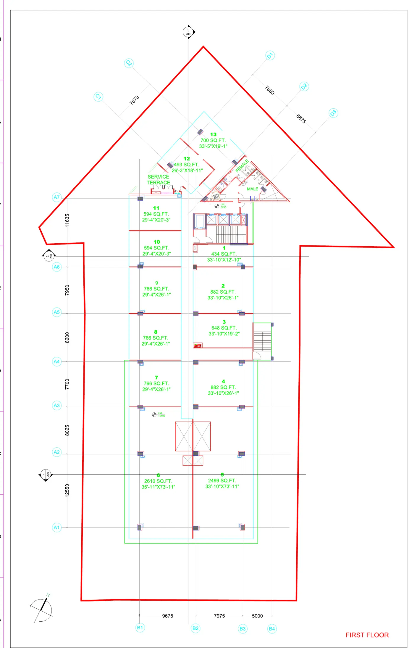
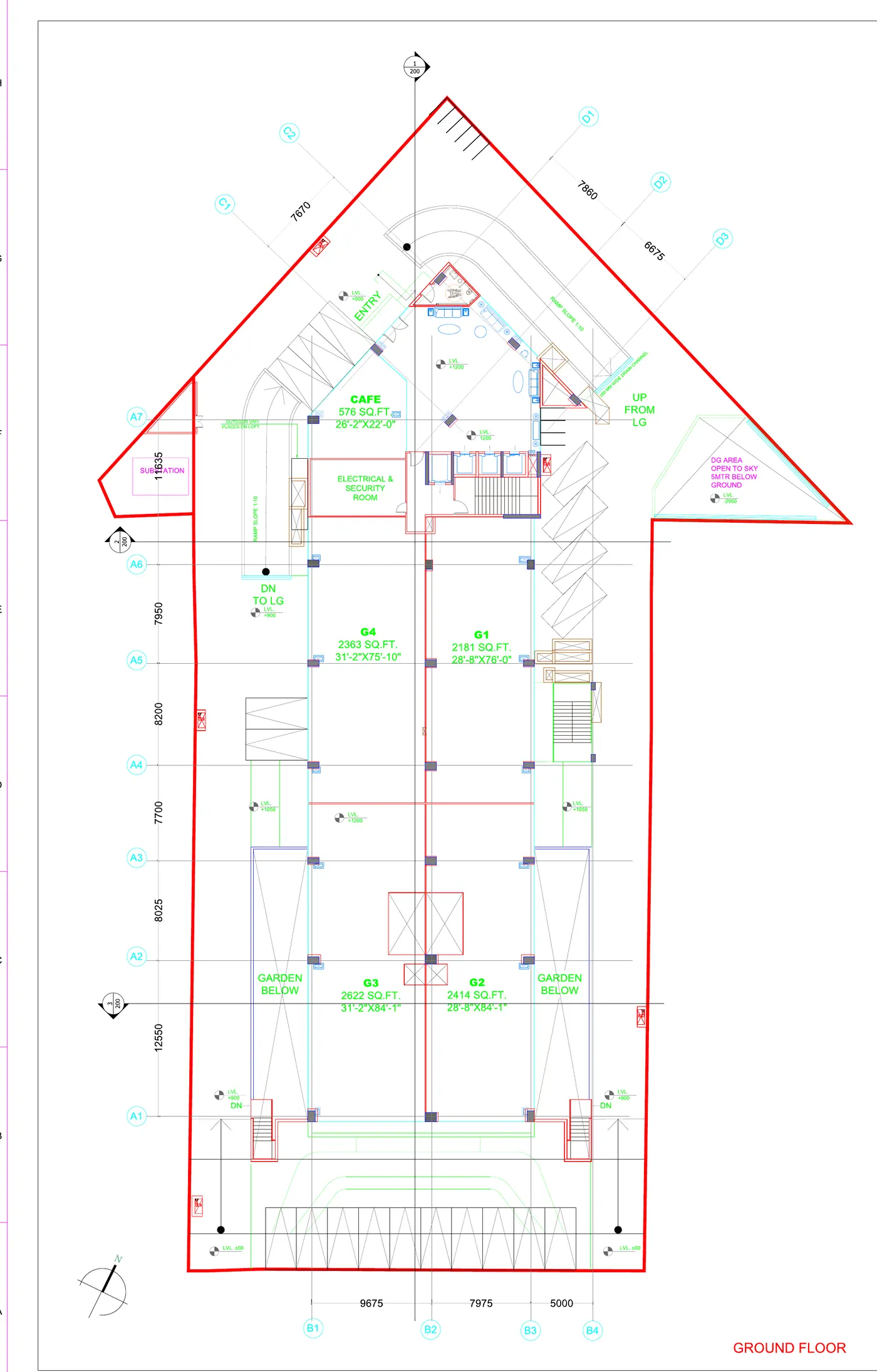
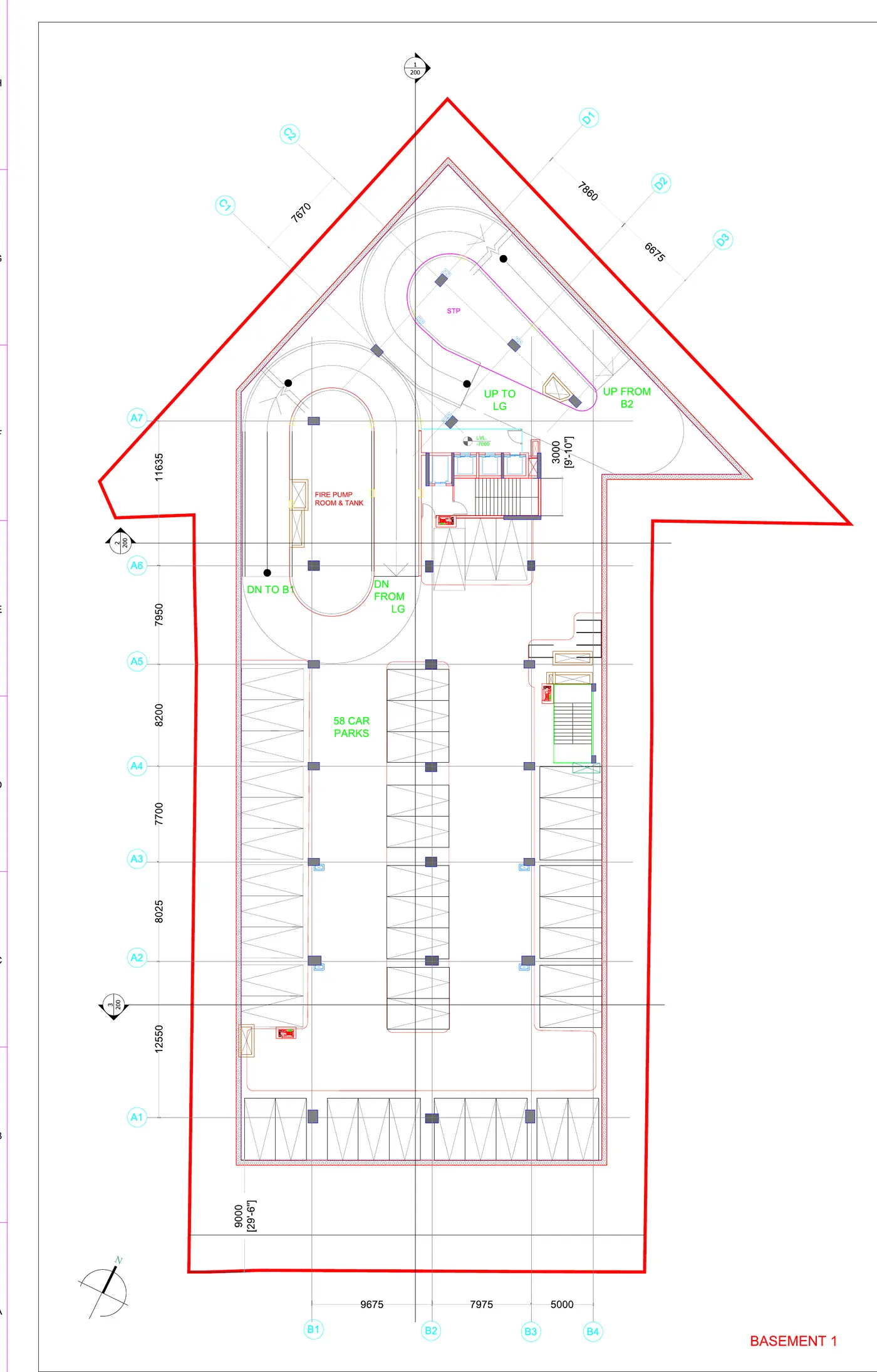
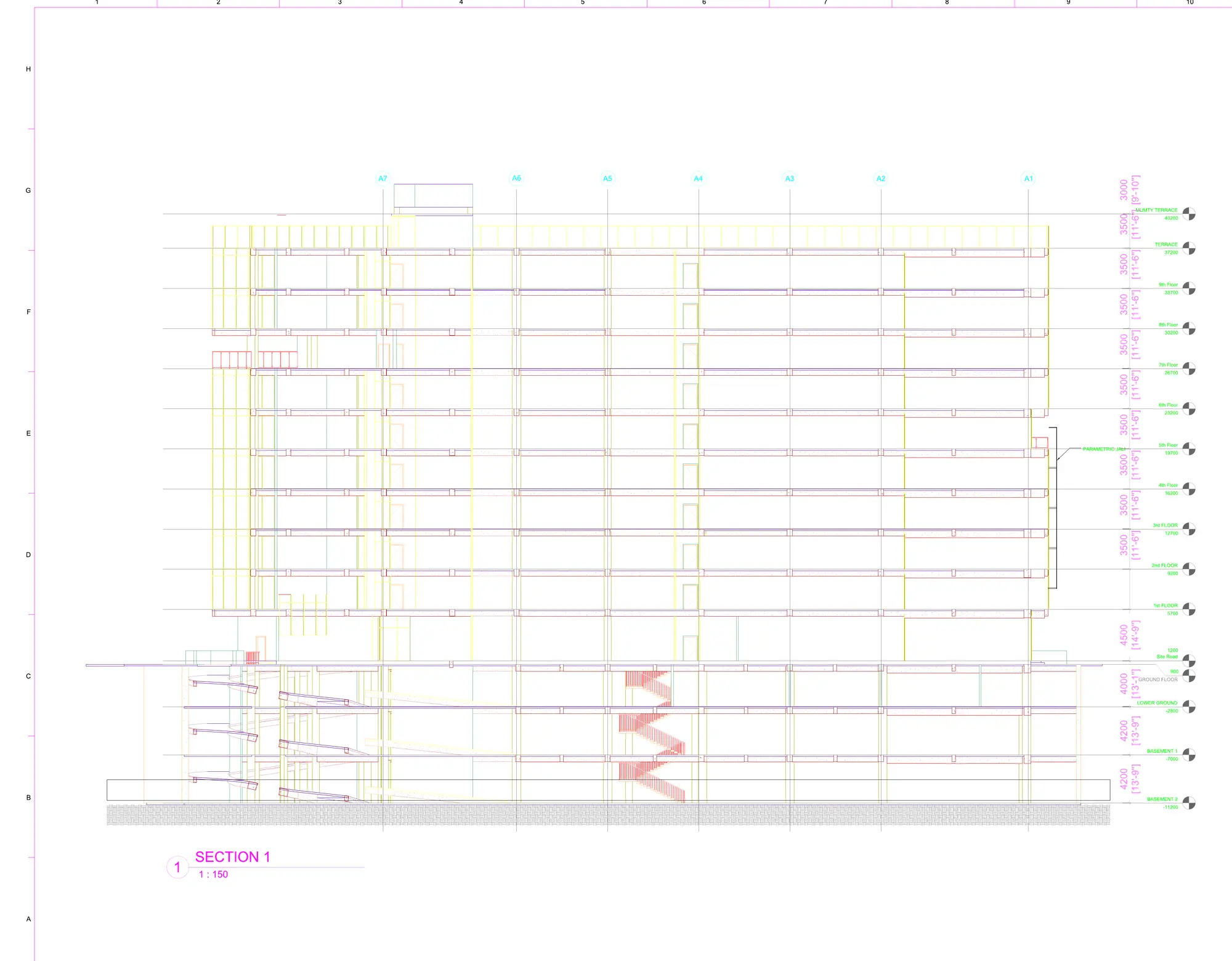
This project arrived as one architectural DWG — 12 sheets. PDF works too.
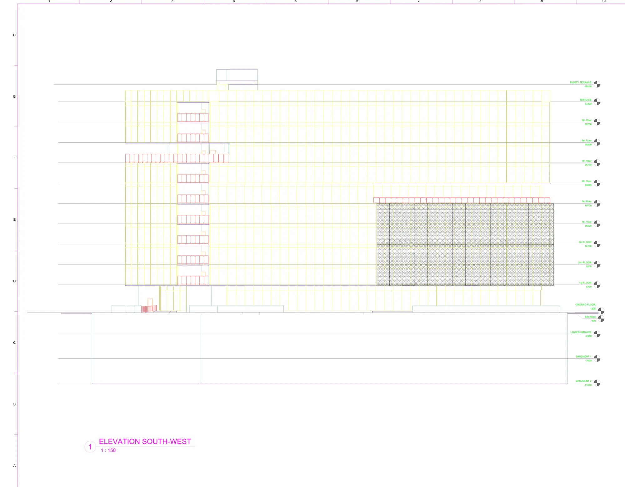 1 / 5
1 / 5First-floor plan — 13 units, areas labelled per unit
The AI agent builds the model and the take-off
32,670 CAD entities · 95 layers · 129 dimensions read automatically. The agent rebuilds the building as a federated BIM — 15,490 elements across 17 storeys, structural + MEP, 12,039 m³ of concrete modelled — and measures the quantities from it.
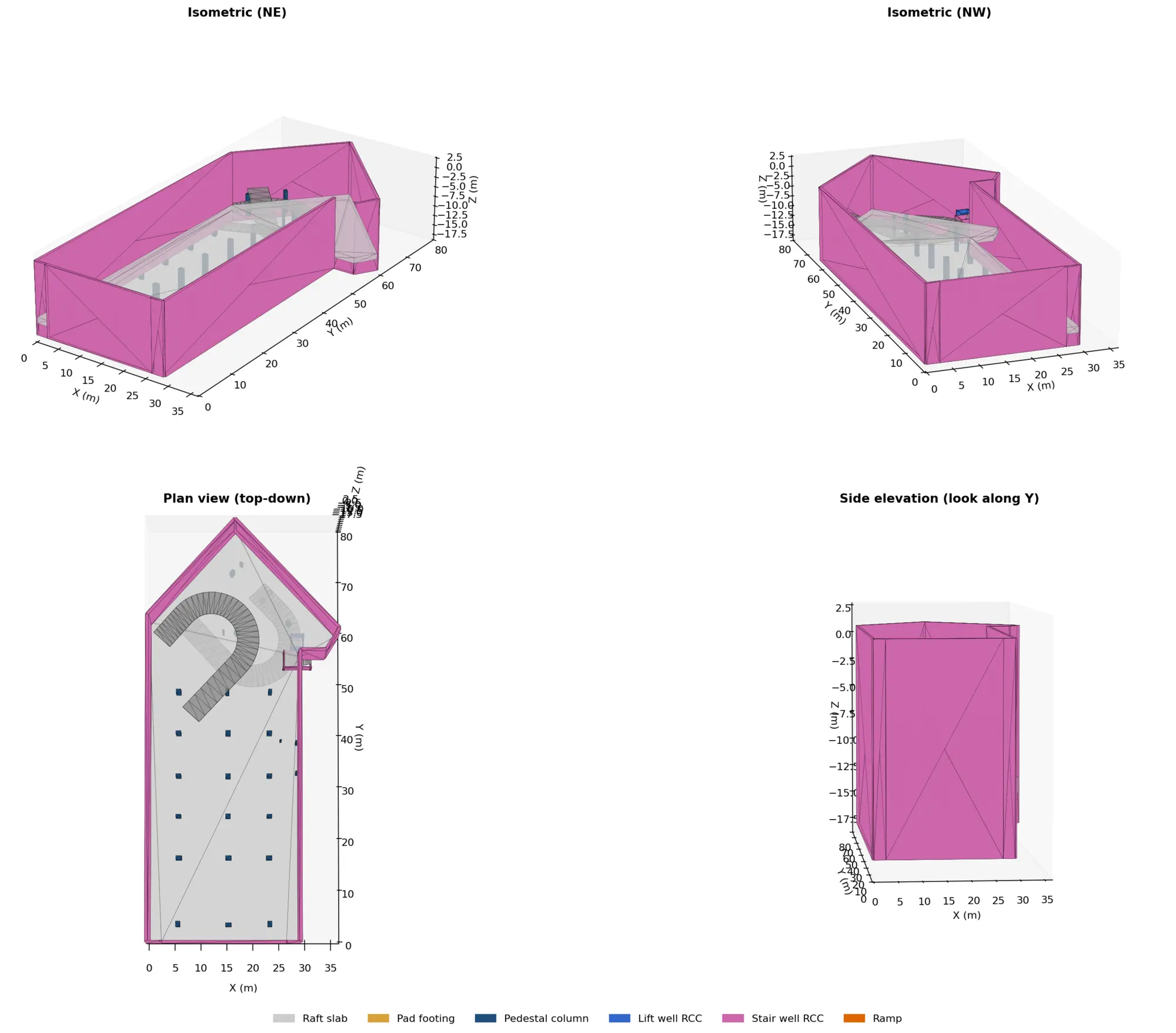
~25 MB — the full federated model, structural + MEP, loads in your browser
Every element carries its source drawing, layer and confidence — click any member inside the viewer to see where it came from.
Open full screen ↗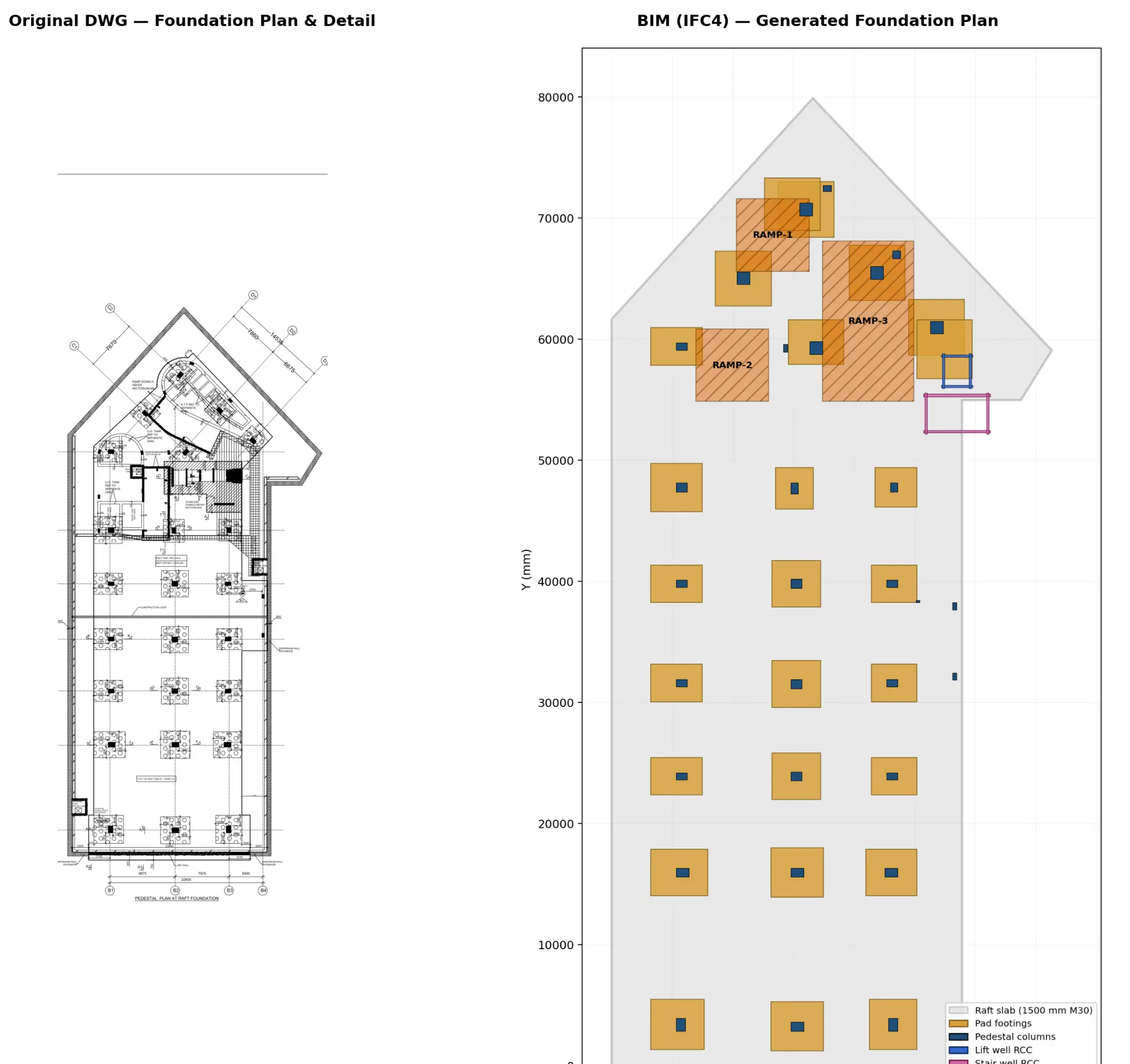 1 / 2
1 / 2Original foundation drawing (left) vs the model the agent rebuilt from it (right) — 26 footings, 30 pedestals, 3 ramps, ~2,134 sqm raft
Released quantities — headline rows
The same table your delivery opens with: quantity, unit, and an M/E basis chip per row. The full workbook is below.
| Item | Qty | Unit | Basis | Method |
|---|---|---|---|---|
| Concrete in structure (modelled) | 12,039 | m³ | M | Solid volumes of modelled members |
| RCC columns, B2 → terrace | 530 | nos | M | Column + framing plans, 17 storeys |
| RCC beams | 1,640 | nos | M | Framing extraction per storey |
| Slab panels | 1,489 | nos | M | Panel polygons, ramp/stair cutouts applied |
| RCC / shear walls | 83 | nos | M | Wall segments from structural layers |
| RCC pad footings + raft | 25 + 2,134 | nos + m² | M | Foundation plan geometry |
| Staircases | 71 | flights | M | 33 stair spans, risers counted per flight |
| Doors, all types | 181 | nos | M | Door schedule, B2 → terrace |
| Curtain-wall / glazing panels | 8,482 | nos | E | Facade block counts — needs facade shop set |
| Wall linework (partitions) | 14,835 | m | E | Plan linework — heights from sections pending |
| Rebar (BBS) | — | t | E | Not measurable without bar bending schedules |
The workbook, browsable
Five sheets of the delivered Excel, on this page.
high-rise_takeoff_sample.xlsx · read-only sample
| A | B | C | D | E | F | |
|---|---|---|---|---|---|---|
| 1 | BOQ item | Unit | Quantity | Basis class | Confidence | Method |
| 2 | RCC pad footings | nos | 25 | Modeled (IFC) | High | Foundation plan geometry |
| 3 | Raft slab | sqm | 2,134 | Modeled (IFC) | High | 10-vertex outline from plan |
| 4 | RCC columns, B2 → terrace | nos | 530 | Modeled (IFC) | High | Column + framing plans, 17 storeys |
| 5 | RCC beams | nos | 1,640 | Modeled (IFC) | High | Framing extraction per storey |
| 6 | Slab panels | nos | 1,489 | Modeled (IFC) | High | Panel polygons, ramp/stair cutouts applied |
| 7 | RCC / shear walls | nos | 83 | Modeled (IFC) | High | Wall segments from structural layers |
| 8 | Staircases | flights | 71 | Modeled (IFC) | High | 33 stair spans, risers counted per flight |
| 9 | Doors, all types | nos | 181 | Schedule | High | Door schedule, B2 → terrace |
| 10 | Curtain-wall mullions | nos | 6,815 | Block count | Medium | Facade block INSERTs |
| 11 | Glazing / system panels | nos | 1,667 | Block count | Medium | Facade block INSERTs |
| 12 | Concrete in structure (modelled) | cum | 12,039 | Modeled (IFC) | Medium | Solid volumes of modelled members |
| 13 | Rebar (BBS) | MT | — | Not measurable | — | Needs bar bending schedules |
Format follows our take-off skill: every line carries a basis class (modeled / schedule / block count / not measurable) and confidence. 15,490 elements modeled, 0 IFC validation errors.
How a run actually happens
A representative run of the same pipeline, hour by hour. Timings vary with set size; recent client deliveries went from drawings on WhatsApp to a live delivery page within a day.
Hour 0
Drawings received on WhatsApp
One architectural DWG, 12 sheets — plans B2 to terrace, section, elevations, door schedule. PDF sets run the same way.
Hour 1
Every sheet rendered and read region by region
The agent plots each sheet and inspects it visually before extraction — tables, title blocks, plans and details are located and classified first, so nothing is parsed blind.
Hour 2
Scale calibrated against printed dimensions
129 printed dimensions read; measurements are accepted only when the drawing's own dimension strings reproduce within tolerance. Every later quantity traces back to this calibration.
Hours 3–5
Elements extracted, floor by floor
32,670 CAD entities across 95 layers become walls, columns, beams, slabs, stairs, doors and facade panels. Visual overlay gates catch bad traces — anything the agent cannot verify against the rendered sheet is re-extracted or flagged, not guessed.
Hours 5–6
The building is rebuilt as a federated BIM
15,490 elements across 17 storeys, structural + MEP, exported as IFC4 with zero validation errors — the model you can open in the viewer below.
Hour 7
Quantities computed and tied out
Take-off measured from the model with IS-1200 conventions. Cross-checks reconcile modelled areas against the drawing's own printed area labels; 2,700+ ambiguous items were routed to the review queue instead of silently resolved.
Hour 8
Delivery issued
Workbook with basis and confidence per row, measured plans, the 3D model, and a private delivery page — the same format as this sample.
What your delivery includes
Item-wise BOQ
Every line carries unit, quantity, basis class and confidence — rates stay with your engineer.
Measurement sheets
L×B×D rows traceable to the drawing with grid references — auditable line by line, IS 1200 conventions.
Interactive 3D model
The rebuilt structure, browsable on a phone, with IFC export on request — open it in any BIM software.
Measured floor plans
Extracted geometry per level — walls by thickness class, columns, openings matched to the schedule.
Assumptions, itemised
Whatever the drawings don't state is estimated with the assumption written on the row — E, never hidden.
Private delivery page
Your project ships behind an access code with workbook, downloads (Excel/CSV/IFC) and a walkthrough video.
An engineer verifies and tunes it
Confidence flags, not blind numbers
Every quantity carries the confidence the agent assigned it — see the Element Take-off sheet above. High-confidence counts pass through; low-confidence ones go to the engineer first.
Review queue, checked line by line
Anything ambiguous — unmapped layers, odd blocks, colliding labels — lands in a review queue. On this project the agent flagged 2,700+ items for human eyes instead of guessing.
Tuned to your drawing conventions
Every firm names layers differently. The engineer tunes the agent's layer mapping to your office standards, so the second drawing set runs better than the first.
Want this on your own project?
Send your drawings — the sanction or architecture set, PDF or DWG — and we’ll send you a quote, with a sample from a similar real job.
Shared privately. Drawings belong to the project owner; identity and title blocks are masked. Please don’t forward the link.